

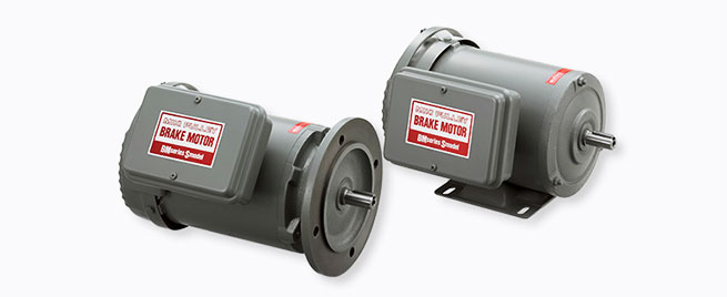
Miki Pulley BMS Models
Specifications
| Model | Motor | Brake | Rotating part moment of inertia [kg・m2] |
Allowable braking energy rate Pbaℓ[W] | Total braking energy [J] |
Operating time | Mass [kg] |
||||||||||
|---|---|---|---|---|---|---|---|---|---|---|---|---|---|---|---|---|---|
| Frame number | Output [kW] 4P |
torque T [N・m] |
Coil(at20℃) | Heat resistance class | Gap | Armature pull-in time ta[s] | Coastdown time | ||||||||||
| Voltage [V] |
Current [A] |
Resistance [Ω] |
Wattage [W] |
Specified value [mm] |
Limit value [mm] |
Simulta- neous off[s] |
DC separate switching off[s] | ||||||||||
| BMS-024-NHBN | 63 | 0.2 | 2 | DC90 | 0.20 | 440 | 18 | B | 0.15~0.25 | 0.40 | 0.8×10⁻³ | 18 | 3.5×10⁷ | 0.04 | 0.1 | 0.08 | 7.5 |
| BMS-024-NHFN | 63 | 0.2 | 2 | DC90 | 0.20 | 440 | 18 | B | 0.15~0.25 | 0.40 | 0.8×10⁻³ | 18 | 3.5×10⁷ | 0.04 | 0.1 | 0.08 | 8.5 |
| BMS-044-NHB | 71 | 0.4 | 4 | DC90 | 0.28 | 324 | 25 | B | 0.15~0.25 | 0.40 | 1.5×10⁻³ | 26.2 | 7.0×10⁷ | 0.05 | 0.1 | 0.08 | 10 |
| BMS-044-NHF | 71 | 0.4 | 4 | DC90 | 0.28 | 324 | 25 | B | 0.15~0.25 | 0.40 | 1.5×10⁻³ | 26.2 | 7.0×10⁷ | 0.05 | 0.1 | 0.08 | 11 |
| BMS-074-HPB | 80 | 0.75 | 8 | DC90 | 0.33 | 270 | 30 | B | 0.20~0.30 | 0.50 | 4.3×10⁻³ | 29.4 | 12.5×10⁷ | 0.05 | 0.14 | 0.09 | 16.5 |
| BMS-074-HPF | 80 | 0.75 | 8 | DC90 | 0.33 | 270 | 30 | B | 0.20~0.30 | 0.50 | 4.3×10⁻³ | 29.4 | 12.5×10⁷ | 0.05 | 0.14 | 0.09 | 19 |
| BMS-154-HPB | 90 | 1.5 | 15 | DC90 | 0.34 | 261 | 31 | B | 0.20~0.30 | 0.60 | 8.1×10⁻³ | 45.8 | 20.0×10⁷ | 0.11 | 0.15 | 0.09 | 23 |
| BMS-154-HPF | 90 | 1.5 | 15 | DC90 | 0.34 | 261 | 31 | B | 0.20~0.30 | 0.60 | 8.1×10⁻³ | 45.8 | 20.0×10⁷ | 0.11 | 0.15 | 0.09 | 26 |
※Totally enclosed fan cooled motors in conformance with JIS C 4210 for 0.2kW・0.4kW motors, and JIS C 4213 for motors over 0.75 kW.(made by Hitachi Industrial Equipment Systems)
※Motor input power sources are three phase, AC 200V/50Hz、AC200V・AC220V/60Hz.
※For the brake motor’s braking frequency tolerance, please refer to the design’s points for confirmation pages. More detailed frequency data depends on load conditions, so please confirm through selective calculation.
Dimensions 1
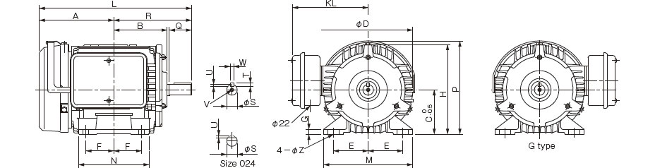
Unit [mm]
| Model | Dimensions of part | ||||||||||||||||||||
|---|---|---|---|---|---|---|---|---|---|---|---|---|---|---|---|---|---|---|---|---|---|
| L | R | A | B | D | KL | H | P | C | F | E | N | M | G | Z | S | W | U | T | Q | V | |
| BMS-024-NHBN | 215 | 103 | 112 | 79 | 130 | 115 | 128 | 134 | 63 | 40 | 50 | 100 | 130 | 3.2 | 7×21 | 11 h6 | - | 1 | - | 23 | - |
| BMS-044-NHB | 244 | 120 | 124 | 87 | 145 | 141 | 143.5 | 150 | 71 | 45 | 56 | 115 | 140 | 3.2 | 7×20 | 14 j6 | 5 | 3 | 5 | 30 | M5×0.8length18 |
| BMS-074-HPB | 299.5 | 140 | 150.5 | 97 | 163 | 148 | 161.5 | 168 | 80 | 50 | 62.5 | 125 | 160 | 3.2 | 10×25 | 19 j6 | 6 | 3.5 | 6 | 40 | M6×1length20 |
| BMS-154-NPB | 329 | 168.5 | 160.5 | 114.5 | 182 | 144 | 178 | 188 | 90 | 62.5 | 70 | 155 | 170 | 10 | 10 | 24 j6 | 8 | 4 | 7 | 50 | M6×1length20 |
Dimensions 2
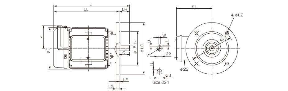
Unit [mm]/div>
| Model | Dimensions of part | |||||||||||||||||
|---|---|---|---|---|---|---|---|---|---|---|---|---|---|---|---|---|---|---|
| L | LR | LL | D | KL | LC | Y | LB | LA | LE | LG | LZ | S | W | U | T | Q | V | |
| BMS-024-NHFN | 241 | 23 | 218 | 130 | 115 | 160 | 70 | 110 | 130 | 3.5 | 8 | 10 | 11 h6 | - | 1 | - | 23 | - |
| BMS-044-NHF | 265 | 30 | 235 | 145 | 134.5 | 160 | 79 | 110 | 130 | 3.5 | 10 | 10 | 14 j6 | 5 | 3 | 5 | 30 | M5×0.8length18 |
| BMS-074-HPF | 305 | 40 | 265 | 163 | 142 | 200 | 88 | 130 | 165 | 3.5 | 12 | 12 | 19 j6 | 6 | 3.5 | 6 | 40 | M6×1length20 |
| BMS-154-HPF | 349 | 50 | 299 | 176 | 144 | 200 | 98 | 130 | 165 | 3.5 | 12 | 12 | 24 j6 | 8 | 4 | 7 | 50 | M6×1length20 |


