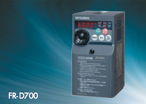
Mitsubishi FR-D700 Series

Simple and compact inverter
Features
Improved reliability and easy maintenance
- Spring clamp terminals provide high reliability and easy wiring.
- Shutoff circuit (hardware) securely provides emergency output shutoffs.
- The inverter with the safety stop function can comply with the safety standards without incurring too much cost.
- Parameter writing/reading can be restricted with a 4-digit password.
- The lives of the cooling fan and capacitor have been extended.
- Using the self-diagnosis function, the part life warning can be output and the degree of deterioration can be monitored to prevent malfunction.
Pursuing the best performance
- The General-purpose magnetic flux vector control and FR-D700 the auto tuning function enable reliable operation in applications that require large starting torque. (150% 1Hz, · 200% 3Hz (3.7K or lower with the slip compensation))
Easy-to-use (pursuing the easy operation)
- The non-slip, adaptable scroll speed setting dial allows for quick jumps or precise increments based on turning · Filter options reduce the electromagnetic noise speed.
- Setting can be made easily from a personal computer with FR Configurator.
- An enclosure surface operation panel, which can be attached on an enclosure surface, is available as an option. Operation panel for the FR-E500 series inverters can be also connected.
- The inverters with 0.4K or higher capacity have built-in regenerative brake transistors, and their usage can be extended to a lift application.
Environmentally friendly
- Filter options reduce the electromagnetic noise generated at the inverter and enables the compliance with the harmonic suppression guidelines of Japan.
Model

Specifications
| Control method | Soft-PWM control, high carrier frequency PWM control (V/F control, General-purpose magnetic flux vector control, Optimum excitation control can be selected) |
|---|---|
| Starting torque | 150% 1Hz, 200% 3Hz (3.7K or lower) with General-purpose magnetic flux vector control and slip compensation |
| Output frequency range | 0.2 to 400Hz |
| Regenerative braking torque * |
0.1K/0.2K·····150%, 0.4K/0.75K·····100%, 1.5K·····50%, 2.2K or higher·····20% |
| Acceleration/deceleration time setting | 0 to 3600s (up to two types of accelerations and decelerations can be set individually.) |
| Multi-speed | 15 speeds |
| Speed command | 0 to 5VDC, 0 to 10VDC, 4 to 20mA, digital input with setting dial, digital setting with operation panel or parameter unit |
| Safety stop | Monitor output S0, output shutoff S1 and S2 |
| Alarm output | 1 changeover contact (230VAC 0.3A. 30VDC 0.3A), open collector output |
| Output signal | One type of open collector output and one type of contact output (1 changeover contact) can be selected from inverter running, up to frequency, frequency detection, output current detection, operation ready, overload warning, fault output, and alarm, etc. |
| Monitor function | One monitored item can be selected from output frequency, motor current (steady or peak value), output voltage, frequency setting value, converter output voltage, regenerative brake duty, and output power, etc. Pulse train output (1440 pulses/s 1mA) |
| Restart after instantaneous power failure | Available (reduced voltage method (frequency search method selectable)) |
| Communication function | RS-485 supported (Modbus-RTU) as standard |
*: Braking torque is the average short-time torque when a motor decelerates to a stop from 60Hz in the shortest time. (It varies with the motor loss.) It is not a continuous regenerative torque. The average deceleration torque becomes lower when a motor decelerates from a frequency higher than the base frequency.
The inverter is not equipped with a built-in brake resistor. Use an option brake resistor for an operation with large regenerative power. Brake unit (FR-BU2) can be also used.


