3D Control FAYb Laser Marker LP-M

CE , FDA Approved
CE : Low Voltage Directive, EMC Directive
Features

HIGH POWER
Panasonic Industrial Devices SUNX’s top-level 40 W high output FAYb laser marker marks or processes deeper and faster on metallic workpieces. Handles an expanded range of laser marker marking / processing applications.

Deep engraving marking / laser processing
Allows deeper and sharper marking and processing to handle demanding applications.
No blade is used for high-quality, stable processing.
- Deep engraving sample [image]
- Laser processing sample [image]
- Image of high-speed deep engraving


High-speed marking
The larger the energy amount sent to the workpiece, the faster and deeper the marking / processing. Takt time reduction greatly enhances productivity.

Advanced environmental resistance
Durable protective structure is a benefit in harsh environments containing dust and water
【IP64 fanless small head】
Fanless small head
Significant improvements in radiation performance enabled a small and fanless head design which is capable of high output. Install with confidence, free from worry about fan clogs.
IP64 Head Protective Design
Employs an inner and outer layer Double Protective Design for better airtightness inside the head. The complete air tight seal prevents dust and water entering from any direction for stable operation on the production floor.

*Anti-dust / waterproof design as per conditions stipulated in IEC / JIS standards.
*Parts must be attached correctly to realize the FAYb laser environmental resistance properties.
【Principles and features of FAYb laser oscillation】
In a revolutionary method, the FAYb laser amplifies a weak laser beam from a master oscillator as it passes through a fiber treated with the element Ytterbium to emit a strong laser beam. Conversion loss is minimal as the FAYb laser amplifies laser beams in the fiber and achieves an excellent beam-to-beam conversion efficiency of approximately 50%. Power consumption is minimized despite high output and contributes to reduced carbon footprint.
Weak pulse laser beams are amplified by absorbing low-output LD beams as they pass through the fiber.

3D-CONTROL
3D Control capability allows marking on various types of products and complicated shapes to meet a large number of application needs.
Enables the best marking on every product type.
The LP-M series contributes to production efficiencies, equipment miniaturization and reduced costs.
High performance Z-axis stroke mechanism
The Z-axis stroke mechanism controls the laser beam focal point in the Z-direction to enable marking on an item with height differences. Marks clearly with no distortion on slanted, curved and stepped surface shapes. Spot average marking enables control of the laser beam spot diameter for uniform marking thickness and depth.


Simple 3D settings: NAVI LINK-3D (Optional)

Easy-to-use software enables you to create marking data by simply overlapping a workpiece shape with the characters and shape data to mark. Check the workpiece from any angle on the image screen to make simple adjustments. For use in overseas factories, English is also available in addition to Japanese.
Advanced marking stability features
Use the displacement sensor for the best marking on every piece
【Displacement input】
Varying workpiece heights during production causes discrepancies in printing quality. The LP-M series can measure workpiece height data directly with the displacement sensor. All workpiece heights can be checked before marking for stable production quality.

Sample marked at a position 2mm away from the correct height

SAFETY
Concern for machine safety has increased as globalization progresses.
A way to safely intercept or stop the laser beam, which is a hazard source in a laser device, is essential. (Compliant with international standard ISO 11553-1)
Two newly mounted safety mechanisms improve both Productivity and Safety.
Laser interceptor [-S type only]

Durability has vastly improved since the first laser interceptor developed. Two outputs can be monitored to check laser interception. Safety is ensured even when the laser power source is on, preventing productivity losses.
Laser interception image

Duplicate interlock circuits

Mounted with 2 interlock circuits instead of one.
A safety relay is also deployed to ensure the laser power source is stopped.

Safety control system structure
International standard ISO 13849-1 (JIS B 9705-1) regulates safety function of safety-related parts of control systems, and requires safeguards be taken for an entire system embedded with a laser marker.

Safe structure with Laser Intercept Feature
Each time a workpiece is loaded or unloaded, the shutter opens and closes. When the shutter is open, the laser intercept mechanism closes to ensure safety. Impacts on production efficiency during mass production are avoided because the laser power source does not need to be stopped each time it opens or closes.
[Operation safety device] Safety magnetic switch, etc.
[2]Safeguards for Maintenance Shutter Safe structure with Laser Intercept Feature
The shutter opens and closes during maintenance or fine tuning. When the shutter is open, the laser intercept mechanism closes to ensure safety. Work efficiency during mass production is not lost because the laser power source does not need to be stopped each time it opens or closes.
[Operation safety device] Safety door switch, etc.
[3]Safeguards for Emergencies Safe structure with Interlock Circuits
In an emergency, forces the laser power source (hazard source) to stop.
[Operation safety device] Emergency stop switch
【Reassuring features used in production】
- Mark energy measurement
- Broken line notification
- Erroneous irradiation detection
- Emergency stop switch
Measures the power when marking, when outside a set range, uses error output to notify.
Stops laser immediately if a severed fiber line is detected.
Stops laser immediately if unforeseen laser irradiation is detected.
Also equipped to the laser marker controller. Can be stopped individually.
【Convenient safety inspection functions】
- Laser output measurement
- Laser output check
- Laser output correction
- Error history view
Measures the current laser output.
Monitor laser output attenuation from the time of purchase.
Calibrate with a commercially available power meter.
Displays error time, date and details.

Advanced user-friendliness
Multiple functions added to the design make work on the factory floor easier.
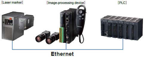
- Supports Ethernet
Simple connection to multiple laser markers and peripherals.
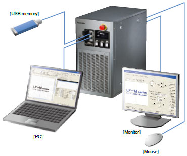
- PC software: laser marker NAVI plus
- Monitor display
- USB connector standard feature
Includes PC software for simple configuration of marking data. Data can even be created off-site (Multiple languages supported). Package includes software to create logos, software to create fonts, and Adobe® Illustrator® Plug-In. Create any kind of data.
*Adobe® and Illustrator® are registered trademarks of Adobe Systems Incorporated.
Connect a monitor and mouse to operate the unit using a large screen.
Settings can be saved to a commercially available USB flash drive source to backup marking conditions, or copy data to multiple laser markers.
*Requires an operation check in advance.
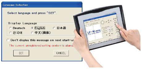
- Multiple language support
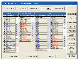
- I/O check monitor
Easily switch among Japanese, English, simplified Chinese, Korean and German.
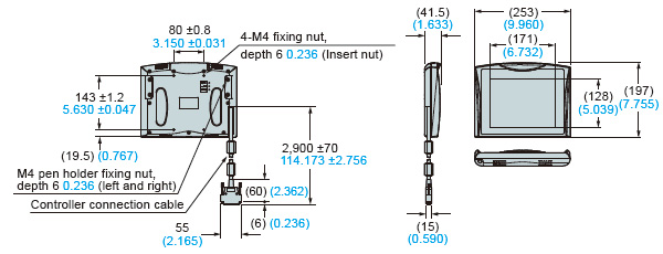
*The console is optional.
Connector I/O can be checked on a monitor. Signals can be quickly checked at equipment startup.
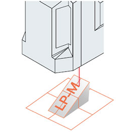
- Guide image display
The marking area or characters to be marked are traced with a red light. Time required for marking can be measured in advance, aiding pre-marking check tasks.
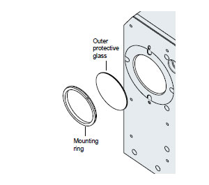
- Protective glass
The laser beam port is constructed of double-layered protective glass. The outer layer of protective glass is removable, and cleaning is easy. If an extra protective glass* procured in advance and used, the production line does not have to be stopped even during cleaning. The laser beam port is protected from dust or damage, reducing maintenance costs.
*Extra protective glass is optional.
Marking
Engine block

Connecting rod
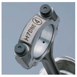
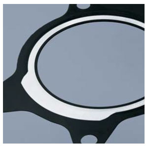
Engine part

coating removal
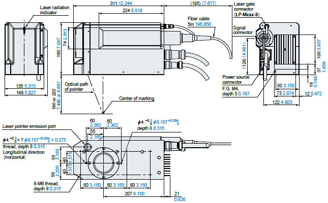
LP-M500
| Model No. | LP-M500 | LP-M500-S | LP-M505 | LP-M505-S | |
|---|---|---|---|---|---|
| Work distance | 190 ± 22 mm 7.480 ± 0.866 in | 220 ± 22 mm 8.661 ± 0.866 in | |||
| Marking field | 120 × 120 mm 4.724 × 4.724 in | 220 × 220 mm 8.661 × 8.661 in | |||
| Marking laser | Class 4 Yb fiber laser; λ= 1,064 nm 0.0419 mil laser | ||||
| Average output*1 | 40 W ± 5 % (pulse oscillation) | ||||
| Guide laser / pointer | Red semiconductor laser; λ= 655 nm 0.026 mil; Class 2 laser: Maximum output 1 mW or less | ||||
| Scanning method | X-, Y- and Z-axis directions; 3D scanning method | ||||
| Scan speed | Maximum 12,000 mm/sec. 472.441 in/sec. | ||||
| Character settings | 0.1 to 120 mm 0.004 to 4.724 in(configurable in 0.001 mm 0.0004 in steps) | 0.1 to 220 mm 0.004 to 8.661 in(configurable in 0.001 mm 0.0004 in steps) | |||
| Setting range (Straight Line,Proportional,Justify) | Character spacing | 0 to 120 mm 0 to 4.724 in | 0 to 220 mm 0 to 8.661 in | ||
| Line pitch | |||||
| Setting range (Arc) | Radius | 0 to 999.999 mm 0 to 39.370 in | |||
| (configurable in 0.001 mm 0.0004 in steps) | |||||
| Angle | -180° to +180°(configurable in 0.01°steps) | ||||
| Line pitch radius | 0 to 120 mm 0 to 4.724 in (configurable in 0.001 mm 0.0004 in steps) | 0 to 220 mm 0 to 8.661 in (configurable in 0.001 mm 0.0004 in steps) | |||
| Logo data | VEC*2, DXF, BMP, HPGL, JPEG, AI, EPS | ||||
| Marking shape | Straight Line, Arc, Propotional, Justify | ||||
| Character types | English uppercase letters, English lowercase letters, numerals, katakana, hiragana, kanji (JIS No. 1 and No. 2 standards), symbols, user-registered characters (up to 50) | ||||
| Barcodes | Code 39, Code 128, ITF, NW-7, JAN / UPC, RSS-14 (GS1 DataBar), RSS (GS1 DataBar) Limited, RSS (GS1 DataBar) Expanded | ||||
| 2D codes | QR Code, Micro QR Code, Data Matrix, GS1 Data Matrix | ||||
| Composite codes | RSS-14 (GS1 DataBar) CC-A, RSS (GS1 DataBar) Limited CC-A, RSS (GS1 DataBar) Expanded CC-A, UCC / EAN COMPOSITE, etc. | ||||
| I/O | Input terminal, Output terminal, I/O connector | ||||
| Interface | VGA port, USB connector A, I/O input and output, RS-232C, Ethernet, Input-output terminal, INTERLOCK*3, displacement sensor, laser gate I/O( -S type only) | ||||
| Displacement sensor input | Analog current input (4 to 20 mA) | ||||
| Cooling method | Head: Naturally air cooling, Controller: Forced air cooling | ||||
| Power supply | 90 to 132 V AC, or 180 to 264 V AC, 50 / 60 Hz(Auto-switching) | ||||
| Power consumption | 580 VA or less (100 V AC), 720 VA or less (200 V AC) | ||||
| Laser gate | Not equipped | Equipped in Head | Not equipped | Equipped in Head | |
| Ambient temperature | 0 to +40 ℃ +32 to +104 ℉( Controller, Head)(No dew condensation or icing allowed) | ||||
| Ambient temperature for storage | -10 to +60 ℃ +14 to +140 ℉( Controller, Head)(No dew condensation or icing allowed) | ||||
| Ambient humidity | 35 % to 85 % RH (Controller, Head)(No dew condensation or icing allowed) | ||||
| Protective structure | IP64*4 | ||||
| Net | Head | 12 kg | |||
| weight | Controller | 28 kg | |||
- Output at product processing edge (at configured power of 100, standard factory settings).
- File format (logo file) that can be used by the laser marker.
- Use a dry contact to connect the INTERLOCK 1 PIN-3 PIN. Deposition on the internal relay contact point can be monitored using INTERLOCK 1-2 PIN and INTERLOCK 2-2 PIN. When 1 PIN-3 PIN is closed, 2 PIN-2 PIN opens.
- The head is IP64 only in regions where an electrical or optical part is deployed.
- To use Export Vec, Adobe® Illustrator® Japanese language Ver. 9/10/CS – CS6 (Japanese OS only), English language CS3 – CS6 (English OS only), or Simplified Chinese CS5 – CS6 (Simplified Chinese OS only) must be installed.
LP-M200
| Model No. | LP-M200 | LP-M200-S | LP-M205 | LP-M205-S | |
|---|---|---|---|---|---|
| Work distance | 190 ? 22 mm 7.480 ? 0.866 in | 220 ? 22 mm 8.661 ? 0.866 in | |||
| Marking field | 120 ? 120 mm 4.724 ? 4.724 in | 220 ? 220 mm 8.661 ? 8.661 in | |||
| Marking laser | Class 4 Yb fiber laser; ?= 1,064 nm 0.0419 mil laser | ||||
| Average output*1 | 16 W ? 5 % (pulse oscillation) | ||||
| Guide laser / pointer | Red semiconductor laser; ?= 655 nm 0.026 mil; Class 2 laser: Maximum output 1 mW or less | ||||
| Scanning method | X-, Y- and Z-axis directions; 3D scanning method | ||||
| Scan speed | Maximum 12,000 mm/sec. 472.441 in/sec. | ||||
| Character settings (character height, width) | 0.1 to 120 mm 0.004 to 4.724 in (configurable in 0.001 mm 0.0004 in steps) | 0.1 to 220 mm 0.004 to 8.661 in (configurable in 0.001 mm 0.0004 in steps) | |||
| Setting range (Straight Line,Proportional,Justify) | Character spacing | 0 to 120 mm 0 to 4.724 in | 0 to 220 mm 0 to 8.661 in | ||
| Line pitch | |||||
| Setting range(Arc) | Radius | 0 to 999.999 mm 0 to 39.370 in (configurable in 0.001 mm 0.0004 in steps) | |||
| Angle | -180? to +180?(configurable in 0.01?steps) | ||||
| Line pitch radius | 0 to 120 mm 0 to 4.724 in (configurable in 0.001 mm 0.0004 in steps) | 0 to 220 mm 0 to 8.661 in (configurable in 0.001 mm 0.0004 in steps) | |||
| Logo data | VEC*2, DXF, BMP, HPGL, JPEG, AI, EPS | ||||
| Marking shape | Straight Line, Arc, Propotional, Justify | ||||
| Character types | English uppercase letters, English lowercase letters, numerals, katakana, hiragana, kanji (JIS No. 1 and No. 2 standards), symbols, user-registered characters (up to 50) | ||||
| Barcodes | Code 39, Code 128, ITF, NW-7, JAN / UPC, RSS-14 (GS1 DataBar), RSS (GS1 DataBar) Limited, RSS (GS1 DataBar) Expanded | ||||
| 2D codes | QR Code, Micro QR Code, Data Matrix, GS1 Data Matrix | ||||
| Composite codes | RSS-14 (GS1 DataBar) CC-A, RSS (GS1 DataBar) Limited CC-A, RSS (GS1 DataBar) Expanded CC-A, UCC / EAN COMPOSITE, etc. | ||||
| I/O | Input terminal, Output terminal, I/O connector | ||||
| Interface | VGA port, USB connector A, I/O input and output, RS-232C, Ethernet, Input-output terminal, INTERLOCK*3, displacement sensor, laser gate I/O( -S type only) | ||||
| Displacement sensor input | Analog current input (4 to 20 mA) | ||||
| Cooling method | Head: Naturally air cooling, Controller: Forced air cooling | ||||
| Power supply | 90 to 132 V AC, or 180 to 264 V AC, 50 / 60 Hz(Auto-switching) | ||||
| Power consumption | 390 VA or less (100 V AC), 510 VA or less (200 V AC) | ||||
| Laser gate | Not equipped | Equipped in Head | Not equipped | Equipped in Head | |
| Ambient temperature | 0 to +40 ? +32 to +104 ?( Controller, Head)(No dew condensation or icing allowed) | ||||
| Ambient temperature for storage | -10 to +60 ? +14 to +140 ?( Controller, Head)(No dew condensation or icing allowed) | ||||
| Ambient humidity | 35 % to 85 % RH (Controller, Head) (No dew condensation or icing allowed) | ||||
| Protective structure | IP64*4 | ||||
| Net | Head | 12 kg | |||
| weight | Controller | 28 kg | |||
- Output at product processing edge (at configured power of 100, standard factory settings).
- File format (logo file) that can be used by the laser marker.
- Use a dry contact to connect the INTERLOCK 1 PIN-3 PIN. Deposition on the internal relay contact point can be monitored using INTERLOCK 1-2 PIN and INTERLOCK 2-2 PIN. When 1 PIN-3 PIN is closed, 2 PIN-2 PIN opens.
- The head is IP64 only in regions where an electrical or optical part is deployed.
- To use Export Vec, Adobe® Illustrator® Japanese language Ver. 9/10/CS – CS6 (Japanese OS only), English language CS3 – CS6 (English OS only), or Simplified Chinese CS5 – CS6 (Simplified Chinese OS only) must be installed.
Software for PC Setting of Laser Marker
| Software | Supported OS |
|---|---|
| Laser Marker Utility*1 | Microsoft Windows® 10 Pro (32 bit / 64 bit) / 8 Pro (32 bit / 64 bit) / 7 Professional (32 bit / 64 bit) / Vista Business (32 bit) / XP Professional (32 bit) |
| NAVILINK-3D*1 (sold separately) | Microsoft Windows® 10 Pro (32 bit / 64 bit) / 8 Pro (32 bit / 64 bit) / 7 Professional (32 bit / 64 bit) / Vista Business (32 bit) / XP Professional (32 bit) |
*1 Windows® 10 Pro, 8 Pro, 7 Professional, Vista Business, and XP Professional are trademarks or registered trademarks of Microsoft Corporation in the United State and other countries.
Head
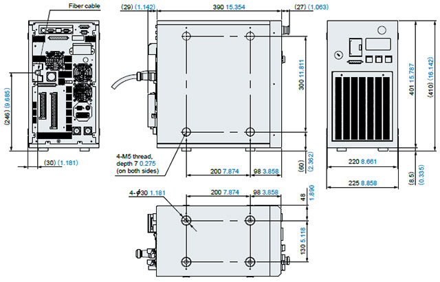
Controller
Console
