

Miki Pulley CF-X Models
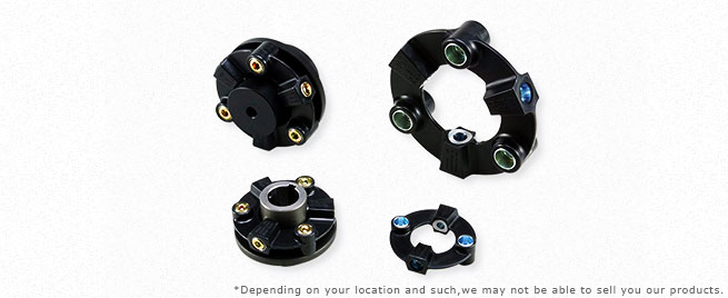
CF-X O0/O1/O2 Types
Specifications]
| Model | Torque | Misalignment | Max. rotation speed [min-1] | Static torsional stiffness [N・m/rad] | |||
|---|---|---|---|---|---|---|---|
| Nominal [N・m] | Max. [N・m] | Parallel [mm] | Angular [°] | Axial [mm] | |||
| CF-X-001 | 15 | 30 | 0.1 | 1 | ±0.5 | 10000 | 3.0×10³ |
| CF-X-002 | 30 | 60 | 0.1 | 1 | ±0.5 | 10000 | 6.0×10³ |
| CF-X-004 | 60 | 120 | 0.1 | 1 | ±0.5 | 8000 | 2.3×10⁴ |
| CF-X-008 | 120 | 250 | 0.1 | 1 | ±0.5 | 7000 | 5.8×10⁴ |
| CF-X-016 | 240 | 500 | 0.1 | 1 | ±0.5 | 6000 | 1.1×10⁵ |
| CF-X-025 | 370 | 800 | 0.1 | 1 | ±0.5 | 5000 | 1.7×10⁵ |
| Model | Moment of inertia [kg・m2] | Mass [kg] |
|---|---|---|
| CF-X-001-O0 | 2.03×10⁻⁵ | 0.04 |
| CF-X-002-O0 | 9.75×10⁻⁵ | 0.1 |
| CF-X-004-O0 | 2.30×10⁻⁴ | 0.2 |
| CF-X-008-O0 | 6.63×10⁻⁴ | 0.3 |
| CF-X-016-O0 | 1.56×10⁻³ | 0.5 |
| CF-X-025-O0 | 2.77×10⁻³ | 0.6 |
| Model | Moment of inertia [kg・m2] | Mass [kg] |
|---|---|---|
| CF-X-001-O1 | 5.25×10⁻⁵ | 0.2 |
| CF-X-002-O1 | 2.20×10⁻⁴ | 0.4 |
| CF-X-004-O1 | 4.83×10⁻⁴ | 0.6 |
| CF-X-008-O1 | 1.49×10⁻³ | 1.3 |
| CF-X-016-O1 | 3.49×10⁻³ | 2.2 |
| CF-X-025-O1 | 7.07×10⁻³ | 3.5 |
| Model | Moment of inertia [kg・m2] | Mass [kg] |
|---|---|---|
| CF-X-001-O2 | 1.22×10⁻⁴ | 0.5 |
| CF-X-002-O2 | 5.74×10⁻⁴ | 0.9 |
| CF-X-004-O2 | 1.19×10⁻³ | 1.4 |
| CF-X-008-O2 | 3.49×10⁻³ | 2.9 |
| CF-X-016-O2 | 9.20×10⁻³ | 5 |
| CF-X-025-O2 | 1.83×10⁻² | 7.9 |
*Max. rotation speed does not take into account dynamic balance.
*Static torsional stiff ness values given are from measurements taken at 20℃ .
*Values for moment of inertia and mass are those when the cylindrical hub and flange hub have pilot bores.
Dimensions
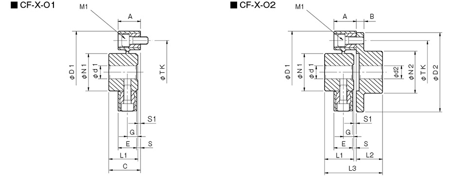
| Model | d1 | d2 | D1 | D2 | N1 | N2 | L1 | L2 | L3 | A | B | C | E | G | S | S1 | M1 | M2 | TK | ||||
|---|---|---|---|---|---|---|---|---|---|---|---|---|---|---|---|---|---|---|---|---|---|---|---|
| Pilot bore | Min. | Max. | Pilot bore | Min. | Max. | ||||||||||||||||||
| CF-X-001 | 8 | 9 | 19 | 8 | 9 | 22 | 57 | 56 | 30 | 36 | 32 | 24 | 57 | 24 | 7 | 33 | 18 | 11 | 3 | 1 | 2-M6 | 2-M6 | 44 |
| CF-X-002 | 10 | 11 | 26 | 9 | 10 | 30 | 88 | 85 | 40 | 45 | 30 | 28 | 62 | 24 | 8 | 34 | 20 | 10 | 4 | 4 | 2-M8 | 2-M8 | 68 |
| CF-X-004 | 12 | 14 | 30 | 11 | 12 | 36 | 100 | 100 | 45 | 55 | 34 | 30 | 66.5 | 25 | 8 | 36.5 | 21 | 12 | 4 | 2.5 | 3-M8 | 3-M8 | 80 |
| CF-X-008 | 12 | 14 | 38 | 15 | 16 | 46 | 125 | 120 | 60 | 70 | 40 | 42 | 85 | 30 | 10 | 43 | 26 | 14 | 4 | 3 | 3-M10 | 3-M10 | 100 |
| CF-X-016 | 15 | 16 | 48 | 19 | 20 | 56 | 155 | 150 | 70 | 85 | 52 | 50 | 105 | 35 | 12 | 55 | 28 | 18 | 7 | 3 | 3-M12 | 3-M12 | 125 |
| CF-X-025 | 15 | 16 | 55 | 19 | 20 | 65 | 175 | 170 | 85 | 100 | 58 | 56 | 117 | 40 | 14 | 61 | 34 | 20 | 6 | 3 | 3-M14 | 3-M14 | 140 |
*Pilot bores are to be drilled into the part. Minimum values for d1 and d2 are given by the minimum bore diameter values in the MIKI PULLEY standard hole-drilling standards and maximum values from the maximum allowable drilled bore diameters.
*The nominal diameters for bolts M1/M2 are equal to the quantity minus the nominal diameter of the screw threads.
*The TK dimension is the bolt mounting pitch diameter of the flange hub or paired mounting part.

CF-X OG Types
Specifications
| Model | Torque | Misalignment | Max. rotation speed [min-1] | Static torsional stiffness [N・m/rad] | Moment of inertia [kg・m2] | Mass [kg] | |||
|---|---|---|---|---|---|---|---|---|---|
| Nominal [N・m] | Max. [N・m] | Parallel [mm] | Angular [°] | Axial [mm] | |||||
| CF-X-001-OG | 15 | 30 | 8.2 | 1 | ±0.5 | 2000 | 1.15×10³ | 4.4×10⁻⁴ | 1.2 |
| CF-X-002-OG | 30 | 60 | 8.2 | 1 | ±0.5 | 2000 | 2.40×10³ | 1.6×10⁻³ | 2.2 |
| CF-X-004-OG | 60 | 120 | 8.2 | 1 | ±0.5 | 2000 | 6.97×10³ | 3.1×10⁻³ | 3.1 |
| CF-X-008-OG | 120 | 250 | 8.1 | 1 | ±0.5 | 2000 | 1.75×10⁴ | 8.6×10⁻³ | 5.8 |
| CF-X-016-OG | 240 | 500 | 7.9 | 1 | ±0.5 | 2000 | 3.15×10⁴ | 2.1×10⁻³ | 9.6 |
| CF-X-025-OG | 370 | 800 | 7.8 | 1 | ±0.5 | 2000 | 5.76×10⁴ | 4.2×10⁻² | 14.6 |
*Max. rotation speed does not take into account dynamic balance.
*Static torsional stiffness values given are from measurements taken at 20℃ .
*Values for moment of inertia and mass are those when the flange hubs have pilot bores and L = 500 mm.
Dimensions]

| Model | d2 | D1 | D2 | N2 | L2 | A | B | E | G | S | S1 | M1 | M2 | R | TK | ||
|---|---|---|---|---|---|---|---|---|---|---|---|---|---|---|---|---|---|
| Pilot bore | Min. | Max. | |||||||||||||||
| CF-X-001-OG | 8 | 9 | 22 | 57 | 56 | 36 | 24 | 24 | 7 | 18 | 11 | 3 | 1 | 2-M6 | 2-M6 | 30 | 44 |
| CF-X-002-OG | 9 | 10 | 30 | 88 | 85 | 45 | 28 | 24 | 8 | 20 | 10 | 4 | 4 | 2-M8 | 2-M8 | 40 | 68 |
| CF-X-004-OG | 11 | 12 | 36 | 100 | 100 | 55 | 30 | 25 | 8 | 21 | 12 | 4 | 2.5 | 3-M8 | 3-M8 | 45 | 80 |
| CF-X-008-OG | 15 | 16 | 46 | 125 | 120 | 70 | 42 | 30 | 10 | 26 | 14 | 4 | 3 | 3-M10 | 3-M10 | 60 | 100 |
| CF-X-016-OG | 19 | 20 | 56 | 155 | 150 | 85 | 50 | 35 | 12 | 28 | 18 | 7 | 3 | 3-M12 | 3-M12 | 70 | 125 |
| CF-X-025-OG | 19 | 20 | 65 | 175 | 170 | 100 | 56 | 40 | 14 | 34 | 20 | 6 | 3 | 3-M14 | 3-M14 | 85 | 140 |
*Pilot bores are to be drilled into the part. Minimum values for d2 are given by the minimum bore diameter values in the MIKI PULLEY standard hole-drilling standards and maximum values from the maximum allowable drilled bore diameters.
*The nominal diameters for bolts M1/M2 are equal to the quantity minus the nominal diameter of the screw threads, where the quantity is for one side.
*The L dimension has a standard length of 1000 mm or less. Dimension L must at least allow enough space for an M1 bolt to be mounted.

CF-X O2-C Types,*Made to order
Specifications]
| Model | Torque | Misalignment | Max. rotation speed [min-1] | Static torsional stiffness [N・m/rad] | Moment of inertia [kg・m2] | Mass [kg] | |||
|---|---|---|---|---|---|---|---|---|---|
| Nominal [N・m] | Max. [N・m] | Parallel [mm] | Angular [°] | Axial [mm] | |||||
| CF-X-001-O2-C | 15 | 30 | 0.1 | 1 | ±0.5 | 10000 | 3.0×10³ | 7.14×10⁻⁵ | 0.2 |
| CF-X-002-O2-C | 30 | 60 | 0.1 | 1 | ±0.5 | 10000 | 6.0×10³ | 3.44×10⁻⁴ | 0.5 |
| CF-X-004-O2-C | 60 | 120 | 0.1 | 1 | ±0.5 | 8000 | 2.3×10⁴ | 7.22×10⁻⁴ | 0.7 |
*Max. rotation speed does not take into account dynamic balance.
*Static torsional stiffness values given are from measurements taken at 20℃ .
*Values for moment of inertia and mass are those when the cylindrical hub and flange hub have the minimum bore diameters.
Dimensions
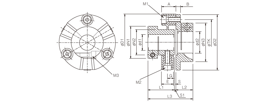
| Model | d1 | d2 | D1 | D2 | N1 | N2 | N3 | L1 | L2 | L3 | A | B | E | G | S | S1 | M1 | M2 | M3 | TK | ||
|---|---|---|---|---|---|---|---|---|---|---|---|---|---|---|---|---|---|---|---|---|---|---|
| Min. | Max. | Min. | Max. | |||||||||||||||||||
| CF-X-001-O2-C | 10 | 16 | 10 | 19 | 57 | 56 | 33 | 30 | 38 | 37 | 24 | 62 | 24 | 7 | 18 | 11 | 3 | 1 | 2-M6 | 2-M6 | 1-M5 | 44 |
| CF-X-002-O2-C | 12 | 25 | 12 | 25 | 88 | 85 | 46 | 40 | 46 | 43 | 28 | 75 | 24 | 8 | 20 | 10 | 4 | 4 | 2-M8 | 2-M8 | 1-M6 | 68 |
| CF-X-004-O2-C | 14 | 28 | 14 | 38 | 100 | 99 | 57 | 45 | 68 | 46.5 | 30 | 79 | 25 | 8 | 21 | 12 | 4 | 2.5 | 3-M8 | 3-M8 | 1-M8 | 80 |
*The nominal diameters for bolts M1, M2, and M3 are equal to the quantity minus the nominal diameter of the screw threads, where the quantity for clamping bolt M3 is for a hub on one side.
*The recommended processing tolerance for paired shafts is the h7 class.

Standard bore diameter
| Model | Standard bore diameter [mm] | |||||||||||||||||
|---|---|---|---|---|---|---|---|---|---|---|---|---|---|---|---|---|---|---|
| 10 | 11 | 12 | 14 | 15 | 16 | 18 | 19 | 20 | 22 | 24 | 25 | 28 | 32 | 30 | 35 | 38 | ||
| CF-X-001-O2-C | d1 | ● | ● | ● | ● | ● | ● | |||||||||||
| d2 | ● | ● | ● | ● | ● | ● | ● | ● | ||||||||||
| CF-X-002-O2-C | d1 | ● | ● | ● | ● | ● | ● | ● | ● | ● | ● | |||||||
| d2 | ● | ● | ● | ● | ● | ● | ● | ● | ● | ● | ||||||||
| CF-X-004-O2-C | d1 | ● | ● | ● | ● | ● | ● | ● | ● | ● | ● | |||||||
| d2 | ● | ● | ● | ● | ● | ● | ● | ● | ● | ● | ● | ● | ● | ● | ||||
Standard Hole-drilling Standards]

| Models compliant with the old JIS standards (Class 2) | Models compliant with the new JIS standards | Models compliant with the new motor standards | ||||||||||||
|---|---|---|---|---|---|---|---|---|---|---|---|---|---|---|
| Nominal bore diameter | Bore diameter (d1, d2) | Keyway width (W1, W2) | Keyway height (T1, T2) | Set screw hole (M) | Nominal bore diameter | Bore diameter (d1, d2) | Keyway width (W1, W2) | Keyway height (T1, T2) | Set screw hole (M) | Nominal bore diameter | Bore diameter (d1, d2) | Keyway width (W1, W2) | Keyway height (T1, T2) | Set screw hole (M) |
| Tolerance | H7, H8 | E9 | +0.30 | – | Tolerance | H7 | H9 | +0.30 | – | Tolerance | G7, F7 | H9 | +0.30 | – |
| 9 | 9+0.0220 | – | – | 2-M4 | – | – | – | – | – | – | – | – | – | – |
| 10 | 10+0.0220 | – | – | 2-M4 | – | – | – | – | – | – | – | – | – | – |
| 11 | 11+0.0180 | – | – | 2-M4 | – | – | – | – | – | – | – | – | – | – |
| 12 | 12+0.0180 | 4+0.050+0.020 | 13.5 | 2-M4 | 12H | 12+0.0180 | 4+0.0300 | 13.8 | 2-M4 | – | – | – | – | – |
| 14 | 14+0.0180 | 5+0.050+0.020 | 16.0 | 2-M4 | 14H | 14+0.0180 | 5+0.0300 | 16.3 | 2-M4 | 14N | 14+0.024+0.006 | 5+0.0300 | 16.3 | 2-M4 |
| 15 | 15+0.0180 | 5+0.050+0.020 | 17.0 | 2-M4 | 15H | 15+0.0180 | 5+0.0300 | 17.3 | 2-M4 | – | – | – | – | – |
| 16 | 16+0.0180 | 5+0.050+0.020 | 18.0 | 2-M4 | 16H | 16+0.0180 | 5+0.0300 | 18.3 | 2-M4 | – | – | – | – | – |
| 17 | 17+0.0180 | 5+0.050+0.020 | 19.0 | 2-M4 | 17H | 17+0.0180 | 5+0.0300 | 19.3 | 2-M4 | – | – | – | – | – |
| 18 | 18+0.0180 | 5+0.050+0.020 | 20.0 | 2-M4 | 18H | 18+0.0180 | 6+0.0300 | 20.8 | 2-M5 | – | – | – | – | – |
| 19 | 19+0.0210 | 5+0.050+0.020 | 21.0 | 2-M4 | 19H | 19+0.0210 | 6+0.0300 | 21.8 | 2-M5 | 19N | 19+0.028+0.007 | 6+0.0300 | 21.8 | 2-M5 |
| 20 | 20+0.0210 | 5+0.050+0.020 | 22.0 | 2-M4 | 20H | 20+0.0210 | 6+0.0300 | 22.8 | 2-M5 | – | – | – | – | – |
| 22 | 22+0.0210 | 7+0.061+0.025 | 25.0 | 2-M6 | 22H | 22+0.0210 | 6+0.0300 | 24.8 | 2-M5 | – | – | – | – | – |
| 24 | 24+0.0210 | 7+0.061+0.025 | 27.0 | 2-M6 | 24H | 24+0.0210 | 8+0.0360 | 27.3 | 2-M6 | 24N | 24+0.028+0.007 | 8+0.0360 | 27.3 | 2-M6 |
| 25 | 25+0.0210 | 7+0.061+0.025 | 28.0 | 2-M6 | 25H | 25+0.0210 | 8+0.0360 | 28.3 | 2-M6 | – | – | – | – | – |
| 28 | 28+0.0210 | 7+0.061+0.025 | 31.0 | 2-M6 | 28H | 28+0.0210 | 8+0.0360 | 31.3 | 2-M6 | 28N | 28+0.028+0.007 | 8+0.0360 | 31.3 | 2-M6 |
| 30 | 30+0.0210 | 7+0.061+0.025 | 33.0 | 2-M6 | 30H | 30+0.0210 | 8+0.0360 | 33.3 | 2-M6 | – | – | – | – | – |
| 32 | 32+0.0250 | 10+0.061+0.025 | 35.5 | 2-M8 | 32H | 32+0.0250 | 10+0.0360 | 35.3 | 2-M8 | – | – | – | – | – |
| 35 | 35+0.0250 | 10+0.061+0.025 | 38.5 | 2-M8 | 35H | 35+0.0250 | 10+0.0360 | 38.3 | 2-M8 | – | – | – | – | – |
| 38 | 38+0.0250 | 10+0.061+0.025 | 41.5 | 2-M8 | 38H | 38+0.0250 | 10+0.0360 | 41.3 | 2-M8 | 38N | 38+0.050+0.025 | 10+0.0360 | 41.3 | 2-M8 |
| 40 | 40+0.0250 | 10+0.061+0.025 | 43.5 | 2-M8 | 40H | 40+0.0250 | 12+0.0430 | 43.3 | 2-M8 | – | – | – | – | – |
| 42 | 42+0.0250 | 12+0.075+0.032 | 45.5 | 2-M8 | 42H | 42+0.0250 | 12+0.0430 | 45.3 | 2-M8 | 42N | 42+0.050+0.025 | 12+0.0430 | 45.3 | 2-M8 |
| 45 | 45+0.0250 | 12+0.075+0.032 | 48.5 | 2-M8 | 45H | 45+0.0250 | 14+0.0430 | 48.8 | 2-M10 | – | – | – | – | – |
| 48 | 48+0.0250 | 12+0.075+0.032 | 51.5 | 2-M8 | 48H | 48+0.0250 | 14+0.0430 | 51.8 | 2-M10 | 48N | 48+0.050+0.025 | 14+0.0430 | 51.8 | 2-M10 |
| 50 | 50+0.0250 | 12+0.075+0.032 | 53.5 | 2-M8 | 50H | 50+0.0250 | 14+0.0430 | 53.8 | 2-M10 | – | – | – | – | – |
| 55 | 55+0.0300 | 15+0.075+0.032 | 60.0 | 2-M10 | 55H | 55+0.0300 | 16+0.0430 | 59.3 | 2-M10 | 55N | 55+0.060+0.030 | 16+0.0430 | 59.3 | 2-M10 |
| 56 | 56+0.0300 | 15+0.075+0.032 | 61.0 | 2-M10 | 56H | 56+0.0300 | 16+0.0430 | 60.3 | 2-M10 | – | – | – | – | – |
| 60 | 60+0.0300 | 15+0.075+0.032 | 65.0 | 2-M10 | 60H | 60+0.0300 | 18+0.0430 | 64.4 | 2-M10 | 60N | 60+0.060+0.030 | 18+0.0430 | 64.4 | 2-M10 |
| 63 | 63+0.0300 | 18+0.075+0.032 | 69.0 | 2-M10 | 18H | 63+0.0300 | 18+0.0430 | 67.4 | 2-M10 | – | – | – | – | – |
| 65 | 65+0.0300 | 18+0.075+0.032 | 71.0 | 2-M10 | 65H | 65+0.0300 | 18+0.0430 | 69.4 | 2-M10 | 65N | 65+0.060+0.030 | 18+0.0430 | 69.4 | 2-M10 |
*The ø11 or below requirement under the new JIS standards and ø11 requirement for the new motor standards are the same as the old JIS standards (class 2).
Distance from set screw edge (Cylinder hub)
| Model | CF-X-001 | CF-X-002 | CF-X-004 | CF-X-008 | CF-X-016 | CF-X-025 |
|---|---|---|---|---|---|---|
| Distance from set screw edge [mm] | 6 | 6 | 6 | 7 | 10 | 10 |
Distance from set screw edge (Flange hub)
| Model | CF-X-001 | CF-X-002 | CF-X-004 | CF-X-008 | CF-X-016 | CF-X-025 |
|---|---|---|---|---|---|---|
| Distance from set screw edge [mm] | 6 | 7 | 7 | 9 | 10 | 10 |


