Miki Pulley 101/CS Models (Clutches)
101 Models
Specifications
| Model | Size | Dynamic friction torque Td [N·m] | Static friction torque Ts [N・m] | Coil (at 20℃) | Heat resistance class | Max. rotation speed (min-1) | Rotating part moment of inertia J | Total work performed until readjustment of the air gap ET [J] | Armature pull-in time time ta [s] | Torque build-up time tp [s] | Torque decaying time td [s] | Mass [kg] | ||||
|---|---|---|---|---|---|---|---|---|---|---|---|---|---|---|---|---|
| Voltage [V] | Capacity [W] | Current [A] | Resistance [Ω] | Rotor [kg・m2] | Armature [kg・m2] | |||||||||||
| 101-06-13G | 06 | 5 | 5.5 | 24 DC | 11 | 0.46 | 52 | B | 8000 | 7.35×10⁻⁵ | 4.23×10⁻⁵ | 36×106 | 0.020 | 0.041 | 0.020 | 0.46 |
| 101-06-15G | 06 | 5 | 5.5 | 24 DC | 11 | 0.46 | 52 | B | 8000 | 7.35×10⁻⁵ | 1.05×10⁻⁴ | 36×106 | 0.020 | 0.041 | 0.020 | 0.66 |
| 101-06-11G | 06 | 5 | 5.5 | 24 DC | 11 | 0.46 | 52 | B | 8000 | 7.35×10⁻⁵ | 6.03×10⁻⁵ | 36×106 | 0.020 | 0.041 | 0.020 | 0.5 |
| 101-08-13G | 08 | 10 | 11 | 24 DC | 15 | 0.63 | 38 | B | 6000 | 2.24×10⁻⁴ | 1.18×10⁻⁴ | 60×106 | 0.023 | 0.051 | 0.030 | 0.83 |
| 101-08-15G | 08 | 10 | 11 | 24 DC | 15 | 0.63 | 38 | B | 6000 | 2.24×10⁻⁴ | 3.00×10⁻⁴ | 60×106 | 0.023 | 0.051 | 0.030 | 1.19 |
| 101-08-11G | 08 | 10 | 11 | 24 DC | 15 | 0.63 | 38 | B | 6000 | 2.24×10⁻⁴ | 1.71×10⁻⁴ | 60×106 | 0.023 | 0.051 | 0.030 | 0.91 |
| 101-10-13G | 10 | 20 | 22 | 24 DC | 20 | 0.83 | 29 | B | 5000 | 6.78×10⁻⁴ | 4.78×10⁻⁴ | 130×106 | 0.025 | 0.063 | 0.050 | 1.5 |
| 101-10-15G | 10 | 20 | 22 | 24 DC | 20 | 0.83 | 29 | B | 5000 | 6.78×10⁻⁴ | 9.45×10⁻⁴ | 130×106 | 0.025 | 0.063 | 0.050 | 2.11 |
| 101-10-11G | 10 | 20 | 22 | 24 DC | 20 | 0.83 | 29 | B | 5000 | 6.78×10⁻⁴ | 6.63×10⁻⁴ | 130×106 | 0.025 | 0.063 | 0.050 | 1.66 |
| 101-12-13G | 12 | 40 | 45 | 24 DC | 25 | 1.09 | 23 | B | 4000 | 2.14×10⁻³ | 1.31×10⁻³ | 250×106 | 0.040 | 0.115 | 0.065 | 2.76 |
| 101-12-15G | 12 | 40 | 45 | 24 DC | 25 | 1.09 | 23 | B | 4000 | 2.14×10⁻³ | 2.75×10⁻³ | 250×106 | 0.040 | 0.115 | 0.065 | 3.8 |
| 101-12-11G | 12 | 40 | 45 | 24 DC | 25 | 1.09 | 23 | B | 4000 | 2.14×10⁻³ | 1.81×10⁻³ | 250×106 | 0.040 | 0.115 | 0.065 | 3.05 |
| 101-16-13G | 16 | 80 | 90 | 24 DC | 35 | 1.46 | 16 | B | 3000 | 6.30×10⁻³ | 4.80×10⁻³ | 470×106 | 0.050 | 0.160 | 0.085 | 5.1 |
| 101-16-15G | 16 | 80 | 90 | 24 DC | 35 | 1.46 | 16 | B | 3000 | 6.30×10⁻³ | 9.05×10⁻³ | 470×106 | 0.050 | 0.160 | 0.085 | 6.9 |
| 101-16-11G | 16 | 80 | 90 | 24 DC | 35 | 1.46 | 16 | B | 3000 | 6.30×10⁻³ | 6.35×10⁻³ | 470×106 | 0.050 | 0.160 | 0.085 | 5.4 |
| 101-20-13G | 20 | 160 | 175 | 24 DC | 45 | 1.88 | 13 | B | 2500 | 1.93×10⁻² | 1.37×10⁻² | 10×108 | 0.090 | 0.250 | 0.130 | 9.3 |
| 101-20-15G | 20 | 160 | 175 | 24 DC | 45 | 1.88 | 13 | B | 2500 | 1.93×10⁻² | 2.65×10⁻² | 10×108 | 0.090 | 0.250 | 0.130 | 13 |
| 101-20-11G | 20 | 160 | 175 | 24 DC | 45 | 1.88 | 13 | B | 2500 | 1.93×10⁻² | 1.90×10⁻² | 10×108 | 0.090 | 0.250 | 0.130 | 10.5 |
| 101-25-13G | 25 | 320 | 350 | 24 DC | 60 | 2.5 | 9.6 | B | 2000 | 4.48×10⁻² | 3.58×10⁻² | 20×108 | 0.115 | 0.335 | 0.210 | 17 |
| 101-25-15G | 25 | 320 | 350 | 24 DC | 60 | 2.5 | 9.6 | B | 2000 | 4.48×10⁻² | 7.45×10⁻² | 20×108 | 0.115 | 0.335 | 0.210 | 23.6 |
| 101-25-11G | 25 | 320 | 350 | 24 DC | 60 | 2.5 | 9.6 | B | 2000 | 4.48×10⁻² | 4.83×10⁻² | 20×108 | 0.115 | 0.335 | 0.210 | 18.7 |
*The dynamic friction torque, Td, is measured at a relative speed of 100 min-1.
*The rotating part moment of inertia and mass are measured for the maximum bore diameter.
Dimensions 101-□-13G
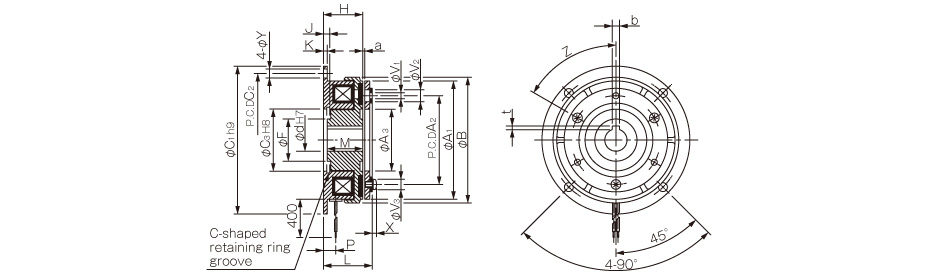
Unit [mm]
| Size | Radial direction dimensions | Axial direction dimensions | |||||||||||||||||||
|---|---|---|---|---|---|---|---|---|---|---|---|---|---|---|---|---|---|---|---|---|---|
| A1 | A2 | A3 | B | C1 | C2 | C3 | F | V1 | V2 | V3 | Y | Z | H | J | K | L | M | P | X | a | |
| 06 | 63 | 46 | 34.5 | 67.5 | 80 | 72 | 35 | 23 | 3-3.1 | 3-6.3 | 3-5.5 | 5 | 6-60° | 24 | 3.5 | 2.1 | 28 | 22 | 7.3 | 2.5 | 0.2±0.05 |
| 08 | 80 | 60 | 41.5 | 85 | 100 | 90 | 42 | 28.5 | 3-4.1 | 3-8 | 3-7 | 6 | 6-60° | 26.5 | 4.3 | 2.6 | 31 | 24 | 8.3 | 2.85 | 0.2±0.05 |
| 10 | 100 | 76 | 51.5 | 106 | 125 | 112 | 52 | 40 | 3-5.1 | 3-10.5 | 3-9 | 7 | 6-60° | 30 | 5 | 3.1 | 36 | 27 | 9 | 3.3 | 0.2±0.05 |
| 12 | 125 | 95 | 61.5 | 133 | 150 | 137 | 62 | 45 | 3-6.1 | 3-12 | 3-11 | 7 | 6-60° | 33.5 | 5.5 | 3.6 | 40.5 | 30 | 9.3 | 3.3 | 0.3+0.05-0.1 |
| 16 | 160 | 120 | 79.5 | 169 | 190 | 175 | 80 | 62 | 3-8.1 | 3-15 | 3-14 | 9.5 | 6-60° | 37.5 | 6 | 4.1 | 46.5 | 34 | 11.7 | 3.5 | 0.3+0.05-0.1 |
| 20 | 200 | 158 | 99.5 | 212.5 | 230 | 215 | 100 | 77 | 3-10.2 | 3-18 | 3-17 | 9.5 | 6-60° | 44 | 7 | 5.1 | 55.5 | 40 | 13.4 | 4.9 | 0.50-0.2 |
| 25 | 250 | 210 | 124.5 | 264 | 290 | 270 | 125 | 100 | 4-12.2 | 4-22 | 4-20 | 11.5 | 8-45° | 51 | 8 | 6.1 | 64 | 47 | 16 | 5.5 | 0.50-0.2 |
Unit [mm]
| Size | Shaft bore dimensions | ||||
|---|---|---|---|---|---|
| dH7 | Models compliant with the new JIS standards | Models compliant with the old JIS standards | |||
| bP9 | t | bE9 | t | ||
| 06 | 12 | 4-0.012-0.042 | 1.5+0.50 | 4+0.050+0.020 | 1.5+0.50 |
| 15 | 5-0.012-0.042 | 2+0.50 | 5+0.050+0.020 | 2+0.50 | |
| 08 | 15 | 5-0.012-0.042 | 2+0.50 | 5+0.050+0.020 | 2+0.50 |
| 20 | 6-0.012-0.042 | 2.5+0.50 | 5+0.050+0.020 | 2+0.50 | |
| 10 | 20 | 6-0.012-0.042 | 2.5+0.50 | 5+0.050+0.020 | 2+0.50 |
| 25 | 8-0.015-0.051 | 3+0.50 | 7+0.061+0.025 | 3+0.50 | |
| 12 | 25 | 8-0.015-0.051 | 3+0.50 | 7+0.061+0.025 | 3+0.50 |
| 30 | 8-0.015-0.051 | 3+0.50 | 7+0.061+0.025 | 3+0.50 | |
| 16 | 30 | 8-0.015-0.051 | 3+0.50 | 7+0.061+0.025 | 3+0.50 |
| 40 | 12-0.018-0.061 | 3+0.50 | 10+0.061+0.025 | 3.5+0.50 | |
| 20 | 40 | 12-0.018-0.061 | 3+0.50 | 10+0.061+0.025 | 3.5+0.50 |
| 50 | 14-0.018-0.061 | 3.5+0.50 | 12+0.075+0.032 | 3.5+0.50 | |
| 25 | 50 | 14-0.018-0.061 | 3.5+0.50 | 12+0.075+0.032 | 3.5+0.50 |
| 60 | 18-0.018-0.061 | 4+0.50 | 15+0.075+0.032 | 5+0.50 | |

Dimensions 101-□-15G
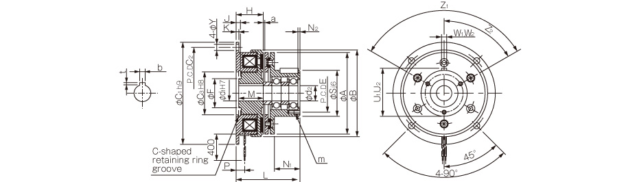
Unit [mm]
| Size | Radial direction dimensions | Axial direction dimensions | |||||||||||||||||||||||
|---|---|---|---|---|---|---|---|---|---|---|---|---|---|---|---|---|---|---|---|---|---|---|---|---|---|
| A | B | C1 | C2 | C3 | E | F | Y | S | Z1 | Z2 | H | J | K | L | M | N1 | N2 | P | U1 | W1 | U2 | W2 | a | m | |
| 06 | 63 | 67.5 | 80 | 72 | 35 | 33 | 23 | 5 | 38 | 3-120° | 60° | 24 | 3.5 | 2.1 | 51.5 | 22 | 20 | 2 | 7.3 | 39.5 | 4 | 39.5 | 4 | 0.2±0.05 | 3-M4×0.7, length: 4 |
| 08 | 80 | 85 | 100 | 90 | 42 | 37 | 28.5 | 6 | 45 | 3-120° | 60° | 26.5 | 4.3 | 2.6 | 60 | 24 | 25 | 2 | 8.3 | 47 | 5 | 47 | 5 | 0.2±0.05 | 3-M4×0.7, length: 6 |
| 10 | 100 | 106 | 125 | 112 | 52 | 47 | 40 | 7 | 55 | 4-90° | 45° | 30 | 5 | 3.1 | 71 | 27 | 30 | 3 | 9 | 57 | 5 | 57.5 | 6 | 0.2±0.05 | 4-M4×0.7, length: 8 |
| 12 | 125 | 133 | 150 | 137 | 62 | 52 | 45 | 7 | 64 | 4-90° | 45° | 33.5 | 5.5 | 3.6 | 86.5 | 30 | 40 | 2 | 9.3 | 67 | 7 | 67 | 8 | 0.3+0.05-0.1 | 4-M4×0.7, length: 8 |
| 16 | 160 | 169 | 190 | 175 | 80 | 62 | 62 | 9.5 | 75 | 6-60° | 30° | 37.5 | 6 | 4.1 | 103.5 | 34 | 50 | 3 | 11.7 | 78 | 7 | 78 | 8 | 0.3+0.05-0.1 | 6-M5×0.8, length: 8 |
| 20 | 200 | 212.5 | 230 | 215 | 100 | 74.5 | 77 | 9.5 | 90 | 4-90° | 45° | 44 | 7 | 5.1 | 124.5 | 40 | 60 | 5 | 13.4 | 93.5 | 10 | 93 | 10 | 0.50-0.2 | 4-M6×1, length: 12 |
| 25 | 250 | 264 | 290 | 270 | 125 | 101.5 | 100 | 11.5 | 115 | 8-45° | 22.5° | 51 | 8 | 6.1 | 145 | 47 | 70 | 6 | 16 | 118.5 | 12 | 118 | 12 | 0.50-0.2 | 8-M6×1, length: 12 |
Unit [mm]
| Size | Shaft bore dimensions | |||||
|---|---|---|---|---|---|---|
| d1H7 | d2 | Models compliant with the new JIS standards | Models compliant with the old JIS standards | |||
| bP9 | t | bE9 | t | |||
| 06 | 12 | 12 | 4-0.012-0.042 | 1.5+0.50 | 4+0.050+0.020 | 1.5+0.50 |
| 08 | 15 | 15 | 5-0.012-0.042 | 2+0.50 | 5+0.050+0.020 | 2+0.50 |
| 10 | 20 | 20 | 6-0.012-0.042 | 2.5+0.50 | 5+0.050+0.020 | 2+0.50 |
| 12 | 25 | 25 | 8-0.015-0.051 | 3+0.50 | 7+0.061+0.025 | 3+0.50 |
| 16 | 30 | 30 | 8-0.015-0.051 | 3+0.50 | 7+0.061+0.025 | 3+0.50 |
| 20 | 40 | 40 | 12-0.018-0.061 | 3+0.50 | 10+0.061+0.025 | 3.5+0.50 |
| 25 | 50 | 50 | 14-0.018-0.061 | 3.5+0.50 | 12+0.075+0.032 | 3.5+0.50 |

Dimensions 101-□-11G
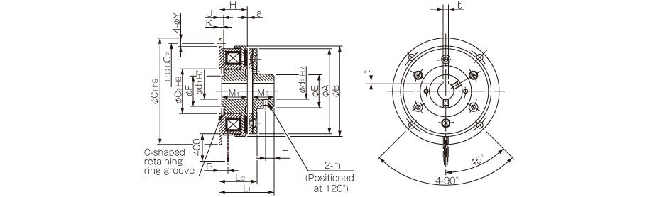
Unit [mm]
| Size | Radial direction dimensions | Axial direction dimensions | |||||||||||||||||
|---|---|---|---|---|---|---|---|---|---|---|---|---|---|---|---|---|---|---|---|
| A | B | C1 | C2 | C3 | E | F | Y | m | H | J | K | L1 | L2 | M1 | M2 | P | T | a | |
| 06 | 63 | 67.5 | 80 | 72 | 35 | 26 | 23 | 5 | M4 | 24 | 3.5 | 2.1 | 43 | 31.5 | 22 | 15 | 7.3 | 6 | 0.2±0.05 |
| 08 | 80 | 85 | 100 | 90 | 42 | 31 | 28.5 | 6 | M5 | 26.5 | 4.3 | 2.6 | 51 | 35 | 24 | 20 | 8.3 | 8 | 0.2±0.05 |
| 10 | 100 | 106 | 125 | 112 | 52 | 41 | 40 | 7 | M5 | 30 | 5 | 3.1 | 61 | 41 | 27 | 25 | 9 | 10 | 0.2±0.05 |
| 12 | 125 | 133 | 150 | 137 | 62 | 49 | 45 | 7 | M6 | 33.5 | 5.5 | 3.6 | 70.5 | 46.5 | 30 | 30 | 9.3 | 12 | 0.3+0.05-0.1 |
| 16 | 160 | 169 | 190 | 175 | 80 | 65 | 62 | 9.5 | M8 | 37.5 | 6 | 4.1 | 84.5 | 53.5 | 34 | 38 | 11.7 | 15 | 0.3+0.05-0.1 |
| 20 | 200 | 212.5 | 230 | 215 | 100 | 83 | 77 | 9.5 | M8 | 44 | 7 | 5.1 | 100.5 | 64.5 | 40 | 45 | 13.4 | 18 | 0.50-0.2 |
| 25 | 250 | 264 | 290 | 270 | 125 | 105 | 100 | 11.5 | M10 | 51 | 8 | 6.1 | 118 | 75 | 47 | 54 | 16 | 22 | 0.50-0.2 |
Unit [mm]
| Size | Shaft bore dimensions | |||||
|---|---|---|---|---|---|---|
| d1H7 | d2H7 | Models compliant with the new JIS standards | Models compliant with the old JIS standards | |||
| bP9 | t | bE9 | t | |||
| 06 | 12 | 12 | 4-0.012-0.042 | 1.5+0.50 | 4+0.050+0.020 | 1.5+0.50 |
| 15 | 15 | 5-0.012-0.042 | 2+0.50 | 5+0.050+0.020 | 2+0.50 | |
| 08 | 15 | 15 | 5-0.012-0.042 | 2+0.50 | 5+0.050+0.020 | 2+0.50 |
| 20 | 20 | 6-0.012-0.042 | 2.5+0.50 | 5+0.050+0.020 | 2+0.50 | |
| 10 | 20 | 20 | 6-0.012-0.042 | 2.5+0.50 | 5+0.050+0.020 | 2+0.50 |
| 25 | 25 | 8-0.015-0.051 | 3+0.50 | 7+0.061+0.025 | 3+0.50 | |
| 12 | 25 | 25 | 8-0.015-0.051 | 3+0.50 | 7+0.061+0.025 | 3+0.50 |
| 30 | 30 | 8-0.015-0.051 | 3+0.50 | 7+0.061+0.025 | 3+0.50 | |
| 16 | 30 | 30 | 8-0.015-0.051 | 3+0.50 | 7+0.061+0.025 | 3+0.50 |
| 40 | 40 | 12-0.018-0.061 | 3+0.50 | 10+0.061+0.025 | 3.5+0.50 | |
| 20 | 40 | 40 | 12-0.018-0.061 | 3+0.50 | 10+0.061+0.025 | 3.5+0.50 |
| 50 | 50 | 14-0.018-0.061 | 3.5+0.50 | 12+0.075+0.032 | 3.5+0.50 | |
| 25 | 50 | 50 | 14-0.018-0.061 | 3.5+0.50 | 12+0.075+0.032 | 3.5+0.50 |
| 60 | 60 | 18-0.018-0.061 | 4+0.50 | 15+0.075+0.032 | 5+0.50 | |

CS Models
Specifications
| Model | Size | Dynamic friction torque Td [N・m] | Static friction torque Ts [N・m] | Coil (at 20℃) | Heat resistance class | Max. rotation speed [min-1] | Rotating part moment of inertia J | Total work performed until readjustment of the air gap ET [J] | Armature pull-in time ta [s] | Torque build-up time tp [s] | Torque decaying time td [s] | Mass [kg] | ||||
|---|---|---|---|---|---|---|---|---|---|---|---|---|---|---|---|---|
| Voltage [V] | Wattage [W] | Current [A] | Resistance [Ω] | Rotor [kg・m2] | Armature [kg・m2] | |||||||||||
| CS-06-33G | 06 | 5 | 5.5 | 24 DC | 11 | 0.46 | 52 | B | 3000 | 7.35×10⁻⁵ | 4.23×10⁻⁵ | 36×106 | 0.020 | 0.041 | 0.020 | 0.50 |
| CS-06-35G | 06 | 5 | 5.5 | 24 DC | 11 | 0.46 | 52 | B | 3000 | 7.35×10⁻⁵ | 1.05×10⁻⁴ | 36×106 | 0.020 | 0.041 | 0.020 | 0.70 |
| CS-06-31G | 06 | 5 | 5.5 | 24 DC | 11 | 0.46 | 52 | B | 3000 | 7.35×10⁻⁵ | 6.03×10⁻⁵ | 36×106 | 0.020 | 0.041 | 0.020 | 0.54 |
| CS-08-33G | 08 | 10 | 11 | 24 DC | 15 | 0.63 | 38 | B | 3000 | 2.24×10⁻⁴ | 1.18×10⁻⁴ | 60×106 | 0.023 | 0.051 | 0.030 | 0.87 |
| CS-08-35G | 08 | 10 | 11 | 24 DC | 15 | 0.63 | 38 | B | 3000 | 2.24×10⁻⁴ | 3.00×10⁻⁴ | 60×106 | 0.023 | 0.051 | 0.030 | 1.23 |
| CS-08-31G | 08 | 10 | 11 | 24 DC | 15 | 0.63 | 38 | B | 3000 | 2.24×10⁻⁴ | 1.71×10⁻⁴ | 60×106 | 0.023 | 0.051 | 0.030 | 0.95 |
| CS-10-33G | 10 | 20 | 22 | 24 DC | 20 | 0.83 | 29 | B | 3000 | 6.78×10⁻⁴ | 4.78×10⁻⁴ | 130×106 | 0.025 | 0.063 | 0.050 | 1.57 |
| CS-10-35G | 10 | 20 | 22 | 24 DC | 20 | 0.83 | 29 | B | 3000 | 6.78×10⁻⁴ | 9.45×10⁻⁴ | 130×106 | 0.025 | 0.063 | 0.050 | 2.18 |
| CS-10-31G | 10 | 20 | 22 | 24 DC | 20 | 0.83 | 29 | B | 3000 | 6.78×10⁻⁴ | 6.63×10⁻⁴ | 130×106 | 0.025 | 0.063 | 0.050 | 1.73 |
| CS-12-33G | 12 | 40 | 45 | 24 DC | 25 | 1.09 | 23 | B | 2000 | 2.14×10⁻³ | 1.31×10⁻³ | 250×106 | 0.040 | 0.115 | 0.065 | 2.89 |
| CS-12-35G | 12 | 40 | 45 | 24 DC | 25 | 1.09 | 23 | B | 2000 | 2.14×10⁻³ | 2.75×10⁻³ | 250×106 | 0.040 | 0.115 | 0.065 | 3.93 |
| CS-12-31G | 12 | 40 | 45 | 24 DC | 25 | 1.09 | 23 | B | 2000 | 2.14×10⁻³ | 1.81×10⁻³ | 250×106 | 0.040 | 0.115 | 0.065 | 3.18 |
| CS-16-33G | 16 | 80 | 90 | 24 DC | 35 | 1.46 | 16 | B | 2000 | 6.30×10⁻³ | 4.80×10⁻³ | 470×106 | 0.050 | 0.160 | 0.085 | 5.3 |
| CS-16-35G | 16 | 80 | 90 | 24 DC | 35 | 1.46 | 16 | B | 2000 | 6.30×10⁻³ | 9.05×10⁻³ | 470×106 | 0.050 | 0.160 | 0.085 | 7.1 |
| CS-16-31G | 16 | 80 | 90 | 24 DC | 35 | 1.46 | 16 | B | 2000 | 6.30×10⁻³ | 6.35×10⁻³ | 470×106 | 0.050 | 0.160 | 0.085 | 5.6 |
| CS-20-33G | 20 | 160 | 175 | 24 DC | 45 | 1.88 | 13 | B | 1500 | 1.93×10⁻² | 1.37×10⁻² | 10×108 | 0.090 | 0.250 | 0.130 | 9.8 |
| CS-25-33G | 25 | 320 | 350 | 24 DC | 72 | 3.00 | 8 | B | 1500 | 4.48×10⁻² | 3.58×10⁻² | 20×108 | 0.115 | 0.335 | 0.210 | 17.5 |
*The dynamic friction torque, Td, is measured at a relative speed of 100 min-1.
*The moment of inertia of a rotating body and mass are measured for the maximum bore diameter.
Dimensions CS-□-33G

Unit [mm]
| Size | Radial direction dimensions | Axial direction dimensions | |||||||||||||||||||||
|---|---|---|---|---|---|---|---|---|---|---|---|---|---|---|---|---|---|---|---|---|---|---|---|
| A1 | A2 | A3 | B | C | F | G1 | G2 | G3 | V1 | V2 | V3 | Y1 | Y2 | H | L1 | L2 | M | J | P | R | X | a | |
| 06 | 63 | 46 | 34.5 | 67.5 | 67.5 | 24 | 42.5 | 50 | 9.5 | 3.1 | 6.3 | 5.5 | 4.5 | 14 | 24 | 31 | 28 | 22 | 5 | 7.3 | 2 | 2.5 | 0.2±0.05 |
| 08 | 80 | 60 | 41.5 | 85 | 85 | 34 | 57.5 | 65 | 11.5 | 4.1 | 8 | 7 | 6.5 | 16 | 26.5 | 34.5 | 31 | 24 | 6 | 8.3 | 2 | 2.85 | 0.2±0.05 |
| 10 | 100 | 76 | 51.5 | 106 | 106 | 40 | 62.5 | 70 | 11.5 | 5.1 | 10.5 | 9 | 6.5 | 16 | 30 | 39.5 | 36 | 27 | 6.5 | 9 | 2 | 3.3 | 0.2±0.05 |
| 12 | 125 | 95 | 61.5 | 133 | 133 | 45 | 77.5 | 85 | 11.5 | 6.1 | 12 | 11 | 6.5 | 16 | 33.5 | 44.5 | 40.5 | 30 | 7.5 | 9.3 | 2 | 3.3 | 0.3+0.05-0.1 |
| 16 | 160 | 120 | 79.5 | 169 | 169 | 58 | 100 | 112 | 18.5 | 8.1 | 15 | 14 | 8.5 | 25 | 37.5 | 50.5 | 46.5 | 34 | 7.5 | 11.7 | 3.2 | 3.5 | 0.3+0.05-0.1 |
| 20 | 200 | 158 | 99.5 | 212.5 | 212 | 75 | 125 | 138 | 18.5 | 10.2 | 18 | 16.2 | 8.5 | 25 | 44 | 60.5 | 55.5 | 40 | 9 | 13.4 | 3 | 5 | 0.50-0.2 |
| 25 | 250 | 210 | 124.5 | 264 | 250 | 100 | 155 | 173 | 24 | 12.2 | 22 | 20 | 12 | 30 | 53 | 69 | 66 | 47 | 9 | 18 | 6 | 4.5 | 0.50-0.2 |
Unit [mm]
| Size | Shaft bore dimensions | ||||
|---|---|---|---|---|---|
| dH7 | Models compliant with the new JIS standards | Models compliant with the old JIS standards | |||
| bP9 | t | bE9 | t | ||
| 6 | 12 | 4-0.012-0.042 | 1.5+0.50 | 4+0.050+0.020 | 1.5+0.50 |
| 8 | 15 | 5-0.012-0.042 | 2+0.50 | 5+0.050+0.020 | 2+0.50 |
| 10 | 20 | 6-0.012-0.042 | 2.5+0.50 | 5+0.050+0.020 | 2+0.50 |
| 12 | 25 | 8-0.015-0.051 | 3+0.50 | 7+0.061+0.025 | 3+0.50 |
| 16 | 30 | 8-0.015-0.051 | 3+0.50 | 7+0.061+0.025 | 3+0.50 |
| 20 | 40 | 12-0.018-0.061 | 3+0.50 | 10+0.061+0.025 | 3.5+0.50 |
| 25 | 50 | 14-0.018-0.061 | 3.5+0.50 | 12+0.075+0.032 | 3.5+0.50 |

Dimensions CS-□-35G

Unit [mm]
| Size | Radial direction dimensions | Axial direction dimensions | ||||||||||||||||||||||||||
|---|---|---|---|---|---|---|---|---|---|---|---|---|---|---|---|---|---|---|---|---|---|---|---|---|---|---|---|---|
| A | B | C | E | F | G1 | G2 | G3 | S | Y1 | Y2 | Z1 | Z2 | H | L1 | L2 | M | J | N1 | N2 | P | R | U1 | W1 | U2 | W2 | a | m | |
| 06 | 63 | 67.5 | 67.5 | 33 | 24 | 42.5 | 50 | 9.5 | 38 | 4.5 | 14 | 3-120° | 0° | 24 | 54.5 | 31.5 | 22 | 5 | 20 | 2 | 7.3 | 2 | 39.5 | 4 | 39.5 | 4 | 0.2±0.05 | 3-M4×0.7, length: 4 |
| 08 | 80 | 85 | 85 | 37 | 34 | 57.5 | 65 | 11.5 | 45 | 6.5 | 16 | 3-120° | 0° | 26.5 | 63.5 | 35 | 24 | 6 | 25 | 2 | 8.3 | 2 | 47 | 5 | 47 | 5 | 0.2±0.05 | 3-M4×0.7, length: 6 |
| 10 | 100 | 106 | 106 | 47 | 40 | 62.5 | 70 | 11.5 | 55 | 6.5 | 16 | 4-90° | 45° | 30 | 74.5 | 41 | 27 | 6.5 | 30 | 3 | 9 | 2 | 57 | 5 | 57.5 | 6 | 0.2±0.05 | 4-M4×0.7, length: 8 |
| 12 | 125 | 133 | 133 | 52 | 45 | 77.5 | 85 | 11.5 | 64 | 6.5 | 16 | 4-90° | 45° | 33.5 | 90.5 | 46.5 | 30 | 7.5 | 40 | 2 | 9.3 | 2 | 67 | 7 | 67 | 8 | 0.3+0.05-0.1 | 4-M4×0.7, length: 8 |
| 16 | 160 | 169 | 169 | 62 | 58 | 100 | 112 | 18.5 | 75 | 8.5 | 25 | 6-60° | 30° | 37.5 | 107.5 | 53.5 | 34 | 7.5 | 50 | 3 | 11.7 | 3.2 | 78 | 7 | 78 | 8 | 0.3+0.05-0.1 | 6-M5×0.8, length: 8 |
Unit [mm]
| Size | Shaft bore dimensions | |||||
|---|---|---|---|---|---|---|
| d1H7 | d2 | Models compliant with the new JIS standards | Models compliant with the old JIS standards | |||
| bP9 | t | bE9 | t | |||
| 6 | 12 | 12 | 4-0.012-0.042 | 1.5+0.50 | 4+0.050+0.020 | 1.5+0.50 |
| 8 | 15 | 15 | 5-0.012-0.042 | 2+0.50 | 5+0.050+0.020 | 2+0.50 |
| 10 | 20 | 20 | 6-0.012-0.042 | 2.5+0.50 | 5+0.050+0.020 | 2+0.50 |
| 12 | 25 | 25 | 8-0.015-0.051 | 3+0.50 | 7+0.061+0.025 | 3+0.50 |
| 16 | 30 | 30 | 8-0.015-0.051 | 3+0.50 | 7+0.061+0.025 | 3+0.50 |

Dimensions CS-□-31G
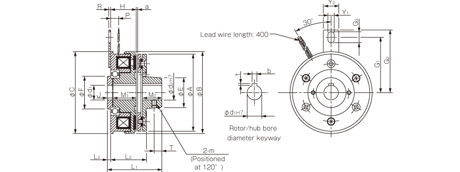
Unit [mm]
| Size | Radial direction dimensions | Axial direction dimensions | ||||||||||||||||||||
|---|---|---|---|---|---|---|---|---|---|---|---|---|---|---|---|---|---|---|---|---|---|---|
| A | B | C | E | F | G1 | G2 | G3 | Y1 | Y2 | m | H | L1 | L2 | L3 | M1 | M2 | J | P | R | T | a | |
| 06 | 63 | 67.5 | 67.5 | 26 | 24 | 42.5 | 50 | 9.5 | 4.5 | 14 | M4 | 24 | 46 | 31.5 | 3 | 22 | 15 | 5 | 7.3 | 2 | 6 | 0.2±0.05 |
| 08 | 80 | 85 | 85 | 31 | 34 | 57.5 | 65 | 11.5 | 6.5 | 16 | M5 | 26.5 | 54.5 | 35 | 3.5 | 24 | 20 | 6 | 8.3 | 2 | 8 | 0.2±0.05 |
| 10 | 100 | 106 | 106 | 41 | 40 | 62.5 | 70 | 11.5 | 6.5 | 16 | M5 | 30 | 64.5 | 41 | 3.5 | 27 | 25 | 6.5 | 9 | 2 | 10 | 0.2±0.05 |
| 12 | 125 | 133 | 133 | 49 | 45 | 77.5 | 85 | 11.5 | 6.5 | 16 | M6 | 33.5 | 74.5 | 46.5 | 4 | 30 | 30 | 7.5 | 9.3 | 2 | 12 | 0.3+0.05-0.1 |
| 16 | 160 | 169 | 169 | 65 | 58 | 100 | 112 | 18.5 | 8.5 | 25 | M8 | 37.5 | 88.5 | 53.5 | 4 | 34 | 38 | 7.5 | 11.7 | 3.2 | 15 | 0.3+0.05-0.1 |
Unit [mm]
| Size | Shaft bore dimensions | |||||
|---|---|---|---|---|---|---|
| d1H7 | d2H7 | Models compliant with the new JIS standards | Models compliant with the old JIS standards | |||
| bP9 | t | bE9 | t | |||
| 6 | 12 | 12 | 4-0.012-0.042 | 1.5+0.50 | 4+0.050+0.020 | 1.5+0.50 |
| 8 | 15 | 15 | 5-0.012-0.042 | 2+0.50 | 5+0.050+0.020 | 2+0.50 |
| 10 | 20 | 20 | 6-0.012-0.042 | 2.5+0.50 | 5+0.050+0.020 | 2+0.50 |
| 12 | 25 | 25 | 8-0.015-0.051 | 3+0.50 | 7+0.061+0.025 | 3+0.50 |
| 16 | 30 | 30 | 8-0.015-0.051 | 3+0.50 | 7+0.061+0.025 | 3+0.50 |