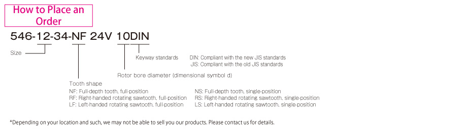
Miki Pulley 546 Models

Specifications
| Model | Size | Torque [N・m] | Coil (at 20℃) | Heat resistance class | Allowable rotation speed of engagement [min-1] | Max. rotation speed [min-1] | Moment of inertia J [kg・m2] | Number of teeth | Armature pull-in time ta [s] | Armature release time tar [s] | Mass [kg] | |||||||
|---|---|---|---|---|---|---|---|---|---|---|---|---|---|---|---|---|---|---|
| Excitation voltage [V] | Wattage [W] | Current [A] | Resistance [Ω] | NF | NS | Sawtooth | Rotor | Armature | Full-depth tooth, full | Sawtooth, full | ||||||||
| 546-12-34 | 12 | 17.5 | DC24 | 13.3 | 0.55 | 44.0 | F | 50 | 30 | 100 | 1500 | 6.6×10⁻⁵ | 6.0×10⁻⁵ | 200 | 25 | 0.035 | 0.040 | 0.5 |
| 546-13-34 | 13 | 25 | DC24 | 18.7 | 0.78 | 31.0 | F | 50 | 30 | 100 | 1500 | 1.5×10⁻⁴ | 1.2×10⁻⁴ | 220 | 30 | 0.040 | 0.050 | 0.9 |
| 546-15-34 | 15 | 50 | DC24 | 21.3 | 0.89 | 27.1 | F | 50 | 30 | 100 | 1500 | 3.7×10⁻⁴ | 3.7×10⁻⁴ | 260 | 36 | 0.060 | 0.060 | 1.5 |
| 546-21-34 | 21 | 100 | DC24 | 27.0 | 1.13 | 21.0 | F | 50 | 30 | 100 | 1500 | 8.7×10⁻⁴ | 5.2×10⁻⁴ | 290 | 36 | 0.080 | 0.070 | 2.4 |
| 546-23-34 | 23 | 250 | DC24 | 36.2 | 1.51 | 15.9 | F | 50 | 30 | 100 | 1500 | 2.06×10⁻³ | 1.85×10⁻³ | 280 | 38 | 0.090 | 0.080 | 3.9 |
| 546-25-34 | 25 | 500 | DC24 | 56.6 | 2.36 | 10.2 | F | 50 | 30 | 100 | 1500 | 4.88×10⁻³ | 4.51×10⁻³ | 250 | 40 | 0.100 | 0.090 | 6.8 |
| 546-31-34 | 31 | 1000 | DC24 | 79.7 | 3.32 | 7.2 | F | 50 | 30 | 100 | 1500 | 1.12×10⁻² | 1.28×10⁻² | 195 | 40 | 0.110 | 0.110 | 11.1 |
| 546-32-34 | 32 | 2200 | DC24 | 114.0 | 4.75 | 5.1 | F | 50 | 30 | 100 | 1500 | 2.87×10⁻² | 2.92×10⁻² | 186 | 40 | 0.120 | 0.130 | 15.3 |
*The armature pull-in and release times are reference values under no load in a stationary state. They are generally longer depending on the size of the load and the operating state when engaged.
*The allowable rotation speeds of engagement NF and NS indicate, respectively, full-depth tooth/full position and full-depth tooth/single position.
Dimensions
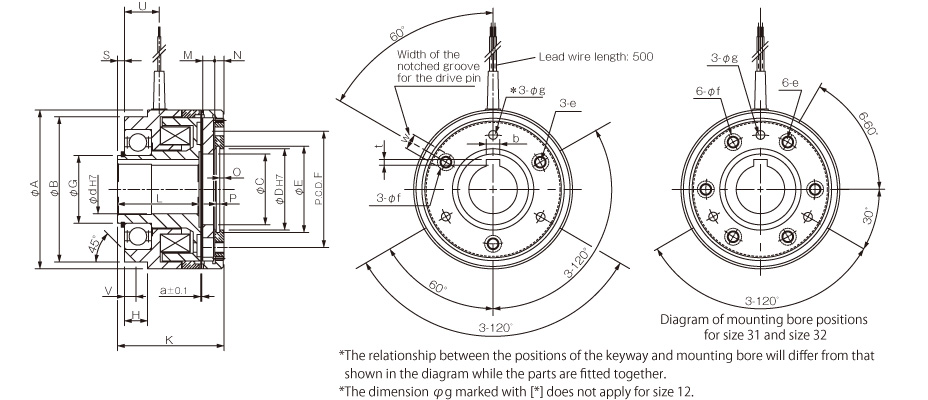
Unit [mm]
| Model | Radial direction dimensions | Axial direction dimensions | ||||||||||||||||||||
|---|---|---|---|---|---|---|---|---|---|---|---|---|---|---|---|---|---|---|---|---|---|---|
| A | B | C | D | E | F | G | e | f | g | H | K | L | M | N | O | P | S | U | V | W | a | |
| 546-12-34 | 57 | 52 | 22.5 | 26 | 27.2 | 36 | 20 | M4 | 8.5 | - | 10 | 43 | 34 | 4.3 | 3.1 | 1.3 | 1.3 | 2.0 | 15 | 4.5 | 5 | 0.2 |
| 546-13-34 | 67 | 58 | 31 | 32 | 33.7 | 46 | 25 | M5 | 8.5 | 4.5 | 11 | 49 | 39 | 4.9 | 3.5 | 1.4 | 1.3 | 2.5 | 16.5 | 5 | 6 | 0.3 |
| 546-15-34 | 82 | 75 | 36.5 | 42 | 44.5 | 60 | 35 | M6 | 10 | 4.5 | 12 | 55 | 42 | 6.1 | 4.8 | 2.2 | 1.9 | 3.5 | 18 | 6 | 8 | 0.3 |
| 546-21-34 | 95 | 88 | 46 | 52 | 55 | 70 | 45 | M8 | 12 | 5.5 | 14 | 63 | 45 | 8.7 | 6.0 | 2.8 | 2.2 | 3.0 | 20 | 6 | 10 | 0.4 |
| 546-23-34 | 114 | 105 | 55 | 62 | 65 | 80 | 55 | M8 | 12 | 7.8 | 18 | 69 | 50 | 9.0 | 6.5 | 3.3 | 2.2 | 3.0 | 24 | 6 | 10 | 0.4 |
| 546-25-34 | 134 | 127 | 68 | 72 | 75 | 95 | 70 | M12 | 15 | 9.5 | 20 | 83 | 61 | 11.0 | 8.4 | 4.3 | 2.7 | 3.0 | 26 | 8 | 10 | 0.4 |
| 546-31-34 | 166 | 152 | 80 | 90 | 93.5 | 120 | 85 | M12 | 15 | 9.5 | 22 | 93.5 | 66 | 13.1 | 11.4 | 5.3 | 3.2 | 3.5 | 31 | 10 | 12 | 0.5 |
| 546-32-34 | 195 | 175 | 95 | 100 | 103.5 | 150 | 100 | M12 | 19 | 11.5 | 24 | 110 | 80 | 14.0 | 11.7 | 6.3 | 3.2 | 4.0 | 38.5 | 10 | 12 | 0.5 |
Unit [mm]
| Size | Shaft bore dimensions | ||||
|---|---|---|---|---|---|
| d H7 | Models compliant with the new JIS standards | Models compliant with the old JIS standards | |||
| b P9 | t+0.50 | b E9 | t+0.50 | ||
| 12 | 10 | 3-0.006-0.031 | 1.2 | 4+0.05+0.02 | 1.5 |
| 13 | 15 | 5-0.012-0.042 | 2 | 5+0.05+0.02 | 2 |
| 15 | 20 | 6-0.012-0.042 | 2.5 | 5+0.05+0.02 | 2 |
| 25 | 8-0.015-0.051 | 3 | 7+0.061+0.025 | 3 | |
| 21 | 25 | 8-0.015-0.051 | 3 | 7+0.061+0.025 | 3 |
| 30 | 8-0.015-0.051 | 3 | 7+0.061+0.025 | 3 | |
| 23 | 30 | 8-0.015-0.051 | 3 | 7+0.061+0.025 | 3 |
| 40 | 12-0.018-0.061 | 3 | 10+0.061+0.025 | 3.5 | |
| 25 | 40 | 12-0.018-0.061 | 3 | 10+0.061+0.025 | 3.5 |
| 50 | 14-0.018-0.061 | 3.5 | 12+0.075+0.032 | 3.5 | |
| 31 | 50 | 14-0.018-0.061 | 3.5 | 12+0.075+0.032 | 3.5 |
| 60 | 18-0.018-0.061 | 4 | 15+0.075+0.032 | 5 | |
| 32 | 60 | 18-0.018-0.061 | 4 | 15+0.075+0.032 | 5 |
| 70 | 20-0.022-0.074 | 4.5 | 18+0.075+0.032 | 6 | |