XGS-C

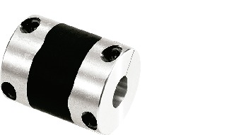
Flexible coupling – High – gain rubber type – Short type
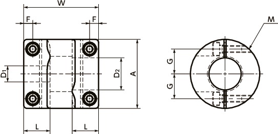
Dimension Drawing
Dimensions/Specifications/CAD
| Part Number | A | L | W | F | G | M | Wrench Torque (N・m) |
|---|---|---|---|---|---|---|---|
| XGS-15C | 15 | 6.5 | 18 | 2.15 | 5 | M1.6 | 0.25 |
| XGS-19C | 19 | 7.7 | 20 | 2.65 | 6.5 | M2 | 0.5 |
| XGS-25C | 25 | 9.5 | 27 | 3.25 | 9 | M2.5 | 1 |
| XGS-30C | 30 | 11 | 30 | 4 | 11 | M3 | 1.5 |
| XGS-34C | 34 | 12 | 35 | 4 | 12.25 | M3 | 1.5 |
| XGS-39C | 39 | 15.5 | 40 | 4.5 | 14.5 | M4 | 2.5 |
| Part Number | Max. Bore Diameter (mm) | Rated Torque* (N・m) | Max. Torque* (N・m) | Max. Rotational (min-1) | Static Torsional Stiffness (N・m/rad) | Max. Lateral Misalignment (mm) | Max. Angular Misalignment (°) | Max. Axial Misalignment (mm) | Mass** (g) |
|---|---|---|---|---|---|---|---|---|---|
| XGS-15C | 6 | 0.5 | 1 | 42000 | 25 | 0.15 | 1.5 | ±0.2 | 7 |
| XGS-19C | 8 | 0.8 | 1.6 | 33000 | 63 | 0.15 | 1.5 | ±0.2 | 12 |
| XGS-25C | 12 | 2.3 | 4.6 | 25000 | 100 | 0.15 | 1.5 | ±0.2 | 25 |
| XGS-30C | 15 | 3.3 | 6.6 | 21000 | 160 | 0.2 | 1.5 | ±0.3 | 39 |
| XGS-34C | 16 | 5.5 | 11 | 18000 | 350 | 0.2 | 1.5 | ±0.3 | 62 |
| XGS-39C | 20 | 7 | 14 | 16000 | 440 | 0.2 | 1.5 | ±0.3 | 85 |
*Adjustment of rated and max. torque specifications for load fluctuations is not required.
However, if operating temperature exceeds 30℃, please adjust rated torque and max. torque as detailed in the table below.
The operational temperature range for XGS is -20℃ to 80℃. For more detailed information, please refer to Selection Guidelines [PDF 171KB].
**Based on the max. shaft bores.
| Part Number | Stock Bores D1-D2 | ||||
|---|---|---|---|---|---|
| XGS-15C | 3-5 | 3-6 | 4-4 | 4-5 | 4-6 |
| 4.5-5 | 5-5 | 5-6 | 6-6 | ||
| XGS-19C | 4-5 | 5-5 | 5-6 | 5-7 | 5-8 |
| 6-6 | 6-6.35 | 6-7 | 6-8 | 6.35-8 | |
| 8-8 | |||||
| XGS-25C | 5-6 | 5-8 | 6-6 | 6-8 | 6-10 |
| 6-11 | 6-12 | 6.35-8 | 6.35-10 | 8-8 | |
| 8-10 | 8-11 | 8-12 | 10-10 | 10-12 | |
| 12-12 | |||||
| XGS-30C | 8-8 | 8-10 | 8-11 | 8-12 | 8-14 |
| 8-15 | 10-10 | 10-11 | 10-12 | 10-14 | |
| 10-15 | 11-12 | 12-12 | 12-14 | 12-15 | |
| 14-14 | 14-15 | 15-15 | |||
| XGS-34C | 8-8 | 8-10 | 8-11 | 8-12 | 8-14 |
| 8-15 | 10-10 | 10-11 | 10-12 | 10-14 | |
| 10-15 | 11-11 | 11-12 | 12-12 | 12-14 | |
| 12-15 | 14-14 | 14-15 | 15-15 | 16-16 | |
| XGS-39C | 10-10 | 10-12 | 10-14 | 10-15 | 10-16 |
| 12-12 | 12-14 | 12-15 | 12-16 | 12-19 | |
| 12-20 | 14-14 | 14-15 | 14-16 | 15-15 | |
| 15-16 | 15-19 | 16-16 | 17-17 | 20-20 | |
- All products come with set screws.
- Recommended tolerance for shaft diameters is h6 and h7.
- Bore and keyway modifications are available on request. Please take advantage of our bore modification services.
For more information please refer to Custom Bore Modifications [PDF 495KB]
Material/Finish
| XGT/XGL/XGS | |
|---|---|
| Hub | A2017 |
| Vibration-absorbing rubber | HNBR |
| Hex Socket Head Cap Screw /Hex Socket Set Screw | SCM435 Ferrosoferric Oxide Film (Black) |
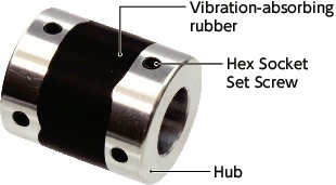
Structure
Set Screw Type
XGT Standard type XGT-C
XGS Short type XGS-C
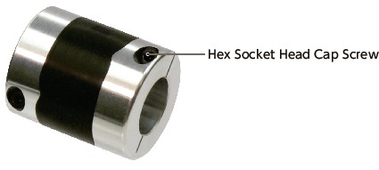
Single Clamping Type
XGT-CS Standard type XGT-C
XGS-CS Short type XGS-C
Double Clamping Type
XGT-C Standard type XGT-C
XGL-C Long type XGL-C
XGS-C Short type XGS-C
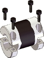
Split-type
Easy to mount and remove screws.
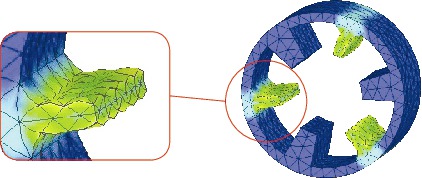
Internal Structure
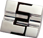
The designed shape of vibration-absorbing rubber achieved high torsional stiffness and high torque according to the newest fi nite element method. This product also succeeds in elongating its life by evenly dispersing the stress focusing on around the inner diameter of the jaw throughout the entire jaw.
Characteristics
- Property
XGT/XGL/XGS Zero Backlash ◎ For servomotor high gain ◎ High Torque ◎ High Torsional Stiffness ○ Allowable Misalignment ○ Vibration absorption characteristics ◎ Allowable Operating Temperature -20℃ to 80℃ ◎: Excellent ○: Very good
- This is a rubber high gain type flexible coupling optimized for actuators.
- Enables you to make high precision positioning in a short time.

- This is a single-piece construction with the two aliminum hubs molded with vibration absorbing rubber.
- About high-gain rubber coupling and reduction of stabilization time
| XGT/XGL/XGS | |
|---|---|
| Servomotor | ◎ |
| Stepping Motor | ◎ |
| General-Purpose Motor | ◎ |
◎: Excellent ○: Very good
Application
Actuator / Surface-mount machine / High precision XY stage / Index table
Selection
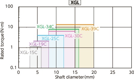
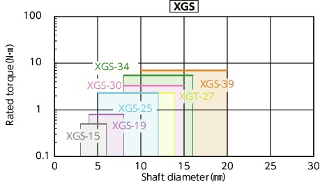
The area bounded by the shaft diameter and rated torque indicates is the selection size.
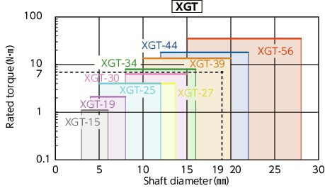
Selection example
In case of selected parameters of shaft diameter of φ19 and load torque of 7 N•m, the selection size is XGT-39C.
| Rated output(W) | Selection size | XGT/XGL | XGS | ||
|---|---|---|---|---|---|
| Diameter of motor shaft (mm) | Rated torque (N・m) | Instantaneous max.torque(N・m) | |||
| 10 | 5-6 | 0.032 | 0.096 | 15C | 15C |
| 20 | 5-6 | 0.064 | 0.19 | 15C | 15C |
| 30 | 5-7 | 0.096 | 0.29 | 19C | 19C |
| 50 | 6-8 | 0.16 | 0.48 | 19C | 19C |
| 100 | 8 | 0.32 | 0.95 | 19C | 25C |
| 200 | 9-14 | 0.64 | 1.9 | 30C | 30C |
| 400 | 14 | 1.3 | 3.8 | 30C | 34C |
| 750 | 16-19 | 2.4 | 7.2 | 39C | – |
*Motor specifications are based on general values. For details, see the motor manufacturer’s catalogs. This is the size for cases where devices such as reduction gears are not used.
Ambient Temperature / Temperature Correction Factor
| Ambient temperature | Temperature correction factor |
|---|---|
| -20℃ to 30℃ | 1.00 |
| 30℃ to 40℃ | 0.80 |
| 40℃ to 60℃ | 0.70 |
| 60℃ to 80℃ | 0.55 |
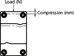
Thrust Reaction Force
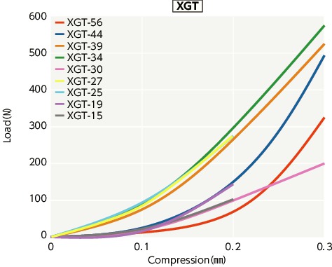
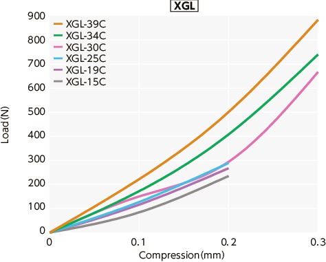
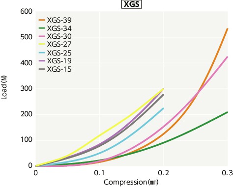
This is a force generated when compressing XGT,XGL,XGS in the shaft direction. As the thrust reaction force becomes smaller, the force acting on the motor also becomes smaller.
Slip Torque
Concerning the sizes shown in the table, please note that the shaft’s slip torque is smaller than the max. torque of XGT-C,XGS-C,XGL-C.
| Part Number | Bore diameter(mm) | ||||||||||||||||
|---|---|---|---|---|---|---|---|---|---|---|---|---|---|---|---|---|---|
| 3 | 4 | 4.5 | 5 | 6 | 6.35 | 7 | 8 | 10 | 11 | 12 | 14 | 15 | 16 | 17 | 19 | 20 | |
| XGT-15C, XGS-15C, XGL-15C | 1 | 1.4 | 1.5 | 1.7 | 2 | ||||||||||||
| XGT-15CS, XGS-15CS | 1 | 1.3 | 1.6 | 1.8 | 1.9 | ||||||||||||
| XGT-19C, XGS-19C, XGL-19C | 2.2 | 2.7 | 3.3 | 3.5 | 3.8 | ||||||||||||
| XGT-19CS, XGS-19CS | 2.3 | 3.1 | 3.1 | 3.3 | 4 | ||||||||||||
| XGT-25C, XGS-25C, XGL-25C | 4.3 | 5.2 | 5.5 | 7 | |||||||||||||
| XGT-25CS, XGS-25CS | 4.7 | 5 | 5.6 | 6.8 | |||||||||||||
| XGT-27CS, XGS-27CS | 3.8 | 5.2 | 7 | ||||||||||||||
| XGT-30C, XGS-30C, XGL-30C | 8.7 | 10.9 | 12 | ||||||||||||||
| XGT-30CS, XGS-30CS | 7.5 | 11 | |||||||||||||||
| XGT-34C, XGS-34C, XGL-34C | 8.7 | 10.9 | 12 | 13 | 15.2 | ||||||||||||
| XGT-34CS, XGS-34CS | 8.3 | 10.5 | 10.7 | 12 | 13.4 | ||||||||||||
| XGT-39C, XGS-39C, XGL-39C | 13.6 | 16.3 | 19 | 20.4 | 21.7 | 23.1 | 25.8 | ||||||||||
| XGT-39CS, XGS-39CS | 13.3 | 15.2 | 17.1 | 20.8 | 18.9 | 25.7 | |||||||||||
| XGT-44C | 16.3 | 19 | 20.4 | 21.7 | 23.1 | 25.8 | 27.2 | ||||||||||
| XGT-44CS | 19.1 | 21.3 | 22.7 | 23.5 | 23.6 | 27.5 | 29.1 | ||||||||||
| XGT-56C | 46 | 58 | 61 | ||||||||||||||
| XGT-56CS | 45 | 50 | 69.4 | ||||||||||||||
These are test values based on the condition of shaft’s dimensional allowance: h7, hardness: from 34-40 HRC, and screw tightening torque of the values described in XGT-C,XGS-C,XGL-C dimensional table.
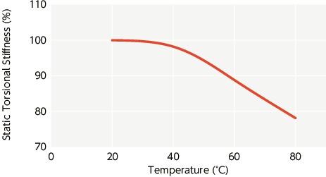
Change in static torsional stiffness due to temperature
This is a value under the condition where the static torsional stiffness at 20°C is 100%.
The change of torsional stiffness within the range of allowable operating temperature is as shown in the graph.
Before using the unit, be aware of the deterioration of responsiveness.
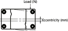
Eccentric Reaction Force
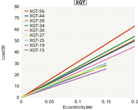
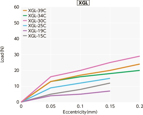
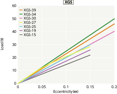
This is a force generated when making XGT,XGL,XGS in eccentric condition. As the eccentric reaction force becomes smaller, the force acting on the shaft bearing also becomes smaller.