MSTS-C

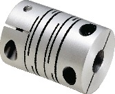
Flexible coupling – Slit – type – Clamping type
Dimension Drawing

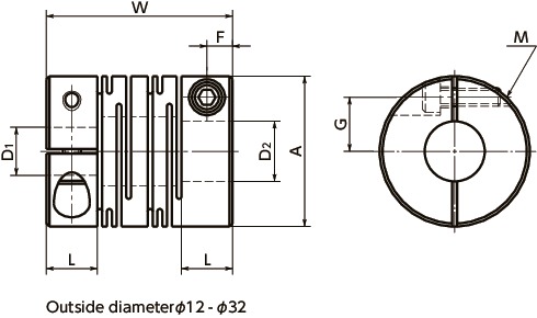
Dimensions/Specifications/CAD
| Part Number | A | L | W | F | G | M | Wrench Torque (N・m) |
|---|---|---|---|---|---|---|---|
| MSTS-12C | 12 | 5 | 18.5 | 2.5 | 4 | M2 | 0.5 |
| MSTS-16C | 16 | 6.5 | 23 | 3.25 | 5 | M2.5 | 1 |
| MSTS-20C | 20 | 7.5 | 26 | 3.75 | 6.5 | M2.5 | 1 |
| MSTS-25C | 25 | 8.5 | 31 | 4.25 | 9 | M3 | 1.5 |
| MSTS-32C | 32 | 12 | 41 | 6 | 11 | M4 | 2.5 |
| MSTS-40C | 40 | 17 | 56 | 8.5 | 14 | M5 | 4 |
| MSTS-50C | 50 | 21 | 71 | 10.5 | 18 | M6 | 8 |
| MSTS-63C | 63 | 26 | 90 | 13 | 24 | M8 | 16 |
| Part Number | Max. Bore Diameter (mm) | Rated Torque* (N・m) | Max. Torque* (N・m) | Max. Rotational (min-1) | Static Torsional Stiffness (N・m/rad) | Max. Lateral Misalignment (mm) | Max. Angular Misalignment (°) | Max. Axial Misalignment (mm) | Mass** (g) |
|---|---|---|---|---|---|---|---|---|---|
| MSTS-12C | 5 | 0.3 | 0.6 | 52000 | 64 | 0.1 | 2 | ±0.2 | 10 |
| MSTS-16C | 6 | 0.5 | 1 | 39000 | 85 | 0.1 | 2 | ±0.3 | 25 |
| MSTS-20C | 8 | 1 | 2 | 31000 | 250 | 0.1 | 2 | ±0.3 | 43 |
| MSTS-25C | 10 | 2 | 4 | 25000 | 330 | 0.15 | 2 | ±0.4 | 78 |
| MSTS-32C | 14 | 3.5 | 7 | 19000 | 850 | 0.15 | 2 | ±0.5 | 170 |
| MSTS-40C | 18 | 8 | 16 | 15000 | 1000 | 0.2 | 2 | ±0.5 | 370 |
| MSTS-50C | 22 | 15 | 30 | 12000 | 1400 | 0.2 | 2 | ±0.5 | 750 |
| MSTS-63C | 30 | 35 | 70 | 10000 | 1800 | 0.2 | 2 | ±0.5 | 1400 |
*Adjustment of rated and max. torque specifications for load fluctuations is not required.
For more detailed information, please refer to Selection Guidelines [PDF 171KB].
**Based on the max. shaft bores.
| Part Number | Stock Bores D1-D2 | ||||
|---|---|---|---|---|---|
| MSTS-12C | 4-4 | 4-5 | 4.5-5 | 5-5 | |
| MSTS-16C | 4.5-5 | 4.5-6 | 5-5 | 5-6 | 6-6 |
| MSTS-20C | 5-6 | 5-6.35 | 5-7 | 5-8 | 6-6 |
| 6-6.35 | 6-7 | 6-8 | 6.35-8 | 8-8 | |
| MSTS-25C | 5-6 | 6-6 | 6-6.35 | 6-8 | 6-10 |
| 6.35-8 | 6.35-10 | 8-8 | 8-9.525 | 8-10 | |
| 9.525-10 | 10-10 | ||||
| MSTS-32C | 8-8 | 8-9.525 | 8-10 | 8-12 | 9.525-10 |
| 9.525-12 | 10-10 | 10-11 | 10-12 | 10-14 | |
| 12-12 | 12-14 | ||||
| MSTS-40C | 8-8 | 8-10 | 10-10 | 12-12 | 12-14 |
| 14-14 | 14-16 | 15-15 | 15-16 | 16-16 | |
| MSTS-50C | 12-14 | 14-14 | 15-15 | 16-16 | 18-18 |
| MSTS-63C | 14-14 | 16-16 | 18-18 | ||
●All products come with set screws.
●Recommended tolerance for shaft diameters is h6 and h7.
●Bore and keyway modifications are available on request. Please take advantage of our bore modification services.
For more information please refer to Custom Bore Modifications [PDF 495KB]
Material/Finish
| MST/MST-C/MST-K | MSTS/MSTS-C/MSTS-K | |
|---|---|---|
| Main Body | A2017 Alumite Treatment | SUS303 |
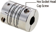
| Hex Socket Set Screw |
SCM435 Ferrosoferric oxide film | SUSXM7 |
| Hex Socket Set Screw |
SCM435 Ferrosoferric oxide film | SUSXM7 |
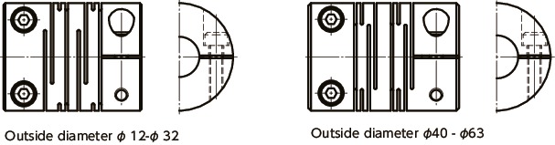
Structure
Set Screw typeMST,MSTS
MSTMade of aluminum alloy
MSTSMade of all stainless steel
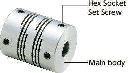
Clamping typeMST-C,MSTS-C
MST-CMade of aluminum alloy
MSTS-CMade of all stainless steel
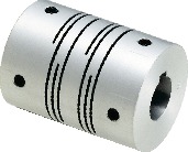
Outside diameter φ40 – φ63
MSTS-C
Outside diameter φ 12 – φ 32
Set Screw + Key typeMST-K,MSTS-K
MST-KMade of aluminum alloy
MSTS-KMade of all stainless steel
Characteristics
- Applicable motors
MST MSTS Servomotor – – Stepping motor ◎ ◎ General-purpose motor ◎ ◎ ◎: Excellent ○: Very good
- Property
MST MSTS Zero Backlash ◎ ◎ High Torque ○ ○ High Torsional Stiffness ○ ○ Allowable Misalignment ○ ○ Corrosion Resistance(All S.S.) – ◎ ◎: Excellent ○: Very good
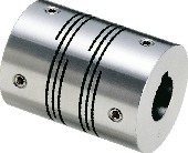
- This is a metal spring coupling with single-piece construction. A slits are made into a cylindrical material.
- A plate spring formed by slits allows eccentricity, angular misalignment, and end-play to be accepted.
- There are two types of units made of aluminum alloy or all stainless steel.
- Wide variation of outside diameter φ 8 – φ 63.
Application
Transport device/XY stage/Parts feeder
Selection
The area bounded by the shaft diameter and rated torque indicates is the selection size.
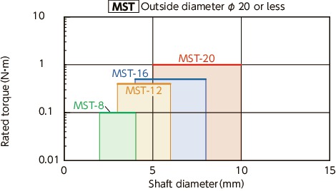
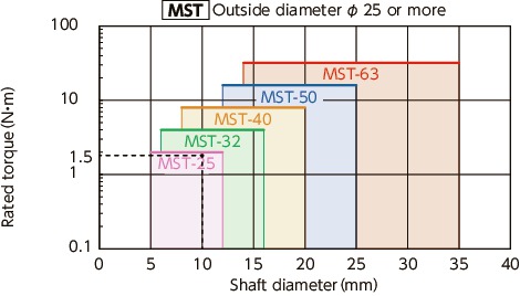
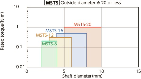

Selection example
In case of selected parameters of shaft diameter of φ10 and load torque of 1.5 N•m, the selected size for MST,MSTS is MST-25,MSTS-25
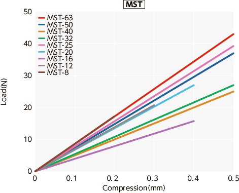
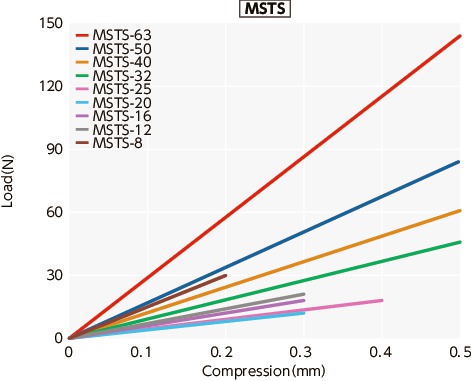
Slip Torque
Thrust Reaction Force
| Part Number | Bore Diameter(mm) | |||||||||||||
|---|---|---|---|---|---|---|---|---|---|---|---|---|---|---|
| 4 | 4.5 | 5 | 6 | 6.35 | 7 | 8 | 9.525 | 10 | 11 | 12 | 14 | 15 | 16 | |
| MST-25C | 3 | 3.6 | ||||||||||||
| MST-32C | 4.1 | 7.3 | ||||||||||||
| MST-40C | 7.1 | 14.3 | 17.8 | 20.3 | 24.4 | |||||||||
| MST-63C | 59.8 | 63.5 | ||||||||||||
| MSTS-12C | 0.4 | 0.5 | ||||||||||||
| MSTS-16C | 0.7 | 0.8 | ||||||||||||
| MSTS-20C | 1.2 | 1.7 | 1.7 | 1.7 | ||||||||||
| MSTS-25C | 0.7 | 0.7 | 0.9 | 1.7 | 3.8 | |||||||||
| MSTS-32C | 1.2 | 2.1 | 2.7 | 2.9 | 5.9 | |||||||||
| MSTS-40C | 8.7 | 12.3 | 12.3 | 14 | ||||||||||
| MSTS-50C | 22.2 | 28.5 | ||||||||||||
| MSTS-63C | 28.8 | 49.5 | ||||||||||||
These are test values based on the condition of shaft’s dimensional allowance: h7, hardness: 34 – 40 HRC, and screw tightening torque of the values described in MST-C,MSTS-C Dimension table.
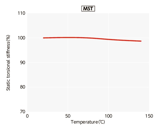
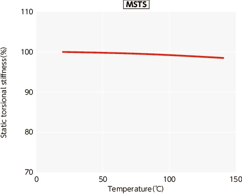
Change in static torsional stiffness due to temperature
This is a value under the condition where the static torsional stiffness at 20°C is 100%.
The change of MST,MSTS in torsional stiffness due to temperature is small and the change in responsiveness is extremely small. However, if the unit is used at higher temperature, be careful about misalignment due to elongation or deflection of the shaft associated with thermal expansion.
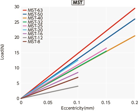
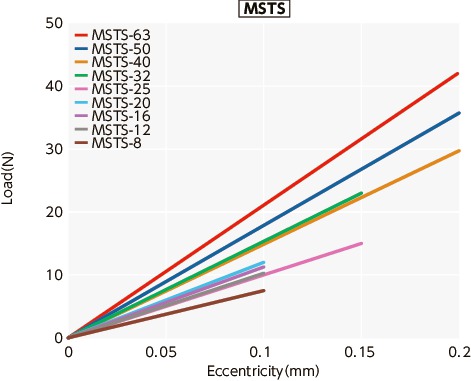
Eccentric Reaction Force