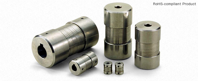
Miki Pulley MM Models
Specifications
| Model | Torque | Misalignment | Max. rotation speed [min-1] | Torsional stiffness [N・m/rad] | Moment of inertia [kg・m2] | Mass [kg] | |||
|---|---|---|---|---|---|---|---|---|---|
| Nominal [N・m] | Max. [N・m] | Parallel [mm] | Angular [°] | Axial [mm] | |||||
| MM-6K | 2.5 | 5 | 0.3 | 3 | +0.6 | 20000 | 143 | 7.65×10⁻⁷ | 0.03 |
| MM-8K | 5 | 10 | 0.3 | 3 | +0.8 | 15000 | 286.5 | 4.08×10⁻⁶ | 0.07 |
| MM-12K | 10 | 20 | 0.4 | 3 | +1.0 | 12000 | 573 | 1.43×10⁻⁵ | 0.14 |
| MM-14K | 10 | 20 | 0.5 | 3 | +1.0 | 10000 | 573 | 2.47×10⁻⁵ | 0.15 |
| MM-16K | 20 | 40 | 0.6 | 3 | +1.2 | 9000 | 1146 | 6.12×10⁻⁵ | 0.30 |
| MM-19K | 20 | 40 | 0.7 | 3 | +1.2 | 8000 | 1146 | 8.42×10⁻⁵ | 0.32 |
| MM-20K | 40 | 80 | 0.7 | 3 | +1.6 | 7000 | 2292 | 1.99×10⁻⁴ | 0.70 |
| MM-24K | 40 | 80 | 0.9 | 3 | +1.6 | 7000 | 2292 | 2.63×10⁻⁴ | 0.75 |
| MM-25K | 90 | 180 | 0.9 | 3 | +2.0 | 6000 | 3438 | 5.66×10⁻⁴ | 1.25 |
| MM-28K | 90 | 180 | 1.0 | 3 | +2.0 | 6000 | 2865 | 5.77×10⁻⁴ | 1.35 |
| MM-30K | 150 | 300 | 1.1 | 3 | +2.5 | 5000 | 4297.5 | 1.39×10⁻⁴ | 2.10 |
| MM-35K | 220 | 440 | 1.2 | 3 | +3.2 | 4500 | 6303 | 3.01×10⁻⁴ | 3.50 |
| Model | Torque | Misalignment | Max. rotation speed [min-1] | Torsional stiffness [N・m/rad] | Moment of inertia [kg・m2] | Mass [kg] | |||
|---|---|---|---|---|---|---|---|---|---|
| Nominal [N・m] | Max. [N・m] | Parallel [mm] | Angular [°] | Axial [mm] | |||||
| MM-6K-S | 2.5 | 5 | 0.3 | 3 | +0.6 | 20000 | 143 | 7.65×10⁻⁷ | 0.03 |
| MM-8K-S | 5 | 10 | 0.3 | 3 | +0.8 | 15000 | 286.5 | 4.08×10⁻⁶ | 0.07 |
| MM-12K-S | 10 | 20 | 0.4 | 3 | +1.0 | 12000 | 573 | 1.43×10⁻⁵ | 0.14 |
| MM-16K-S | 20 | 40 | 0.6 | 3 | +1.2 | 9000 | 1146 | 6.12×10⁻⁵ | 0.30 |
| MM-20K-S | 40 | 80 | 0.7 | 3 | +1.6 | 7000 | 2292 | 1.99×10⁻⁴ | 0.70 |
| MM-25K-S | 90 | 180 | 0.9 | 3 | +2.0 | 6000 | 3438 | 5.66×10⁻⁴ | 1.25 |
*Max. rotation speed does not take into account dynamic balance.
*The moment of inertia and mass are measured for the maximum bore diameter.
Dimensions

Unit [mm]
| Model | d1, d2 | D | L | L1 | E | F | ||
|---|---|---|---|---|---|---|---|---|
| Pilot bore | Min. | Max. | ||||||
| MM-6K | 2.5 | 3 | 8 | 16 | 20 | 6 | 11 | 15.5 |
| MM-8K | 3.5 | 4 | 8 | 21 | 35 | 11 | 13 | 19 |
| MM-12K | 5.5 | 6 | 12 | 26 | 50 | 16.5 | 16.5 | 24 |
| MM-14K | 5.5 | 7 | 14 | 30 | 50 | 16.5 | 20.5 | 28 |
| MM-16K | 5.5 | 10 | 16 | 35 | 65 | 22 | 22.4 | 32 |
| MM-19K | 5.5 | 10 | 19 | 38 | 65 | 22 | 26.4 | 36 |
| MM-20K | 5.5 | 10 | 20 | 45 | 80 | 27 | 28 | 40 |
| MM-24K | 5.5 | 14 | 24 | 48 | 80 | 27 | 33 | 45 |
| MM-25K | 5.5 | 14 | 25 | 55 | 100 | 33.5 | 35 | 50 |
| MM-28K | 5.5 | 14 | 28 | 55 | 100 | 33.5 | 37 | 52 |
| MM-30K | 5.5 | 16 | 30 | 65 | 125 | 40 | 40.8 | 60 |
| MM-35K | 5.5 | 20 | 35 | 75 | 150 | 48 | 46 | 70 |
Unit [mm]
| Model | d1, d2 | D | L | L1 | E | F | ||
|---|---|---|---|---|---|---|---|---|
| Pilot bore | Min. | Max. | ||||||
| MM-6K-S | 2.5 | 3 | 8 | 17 | 25 | 9 | 11 | 15.5 |
| MM-8K-S | 3.5 | 4 | 8 | 21 | 35 | 11 | 13 | 19 |
| MM-12K-S | 5.5 | 6 | 12 | 26 | 50 | 16.5 | 16.5 | 24 |
| MM-16K-S | 5.5 | 10 | 16 | 35 | 65 | 22 | 22.4 | 32 |
| MM-20K-S | 5.5 | 10 | 20 | 45 | 80 | 27 | 28 | 40 |
| MM-25K-S | 5.5 | 14 | 25 | 55 | 100 | 32.5 | 35 | 50 |
*Pilot bores are to be drilled into the part.
Standard Hole-drilling Standards
Unit [mm]
| Models compliant with the old JIS standards (Class 2) | Models compliant with the new JIS standards | Models compliant with the new motor standards | ||||||||||||
|---|---|---|---|---|---|---|---|---|---|---|---|---|---|---|
| Nominal bore diameter | Bore diameter (d1, d2) | Keyway width (W1, W2) | Keyway height (T1, T2) | Set screw hole (M) | Nominal bore diameter | Bore diameter (d1, d2) | Keyway width (W1, W2) | Keyway height (T1, T2) | Set screw hole (M) | Nominal bore diameter | Bore diameter (d1, d2) | Keyway width (W1, W2) | Keyway height (T1, T2) | Set screw hole (M) |
| Tolerance | H7, H8 | E9 | +0.30 | — | Tolerance | H7 | H9 | +0.30 | — | Tolerance | G7 | H9 | +0.30 | — |
| 4 | 4+0.0180 | — | — | 2-M3 | — | — | — | — | — | — | — | — | — | — |
| 5 | 5+0.0180 | — | — | 2-M3 | — | — | — | — | — | — | — | — | — | — |
| 6 | 6+0.0180 | — | — | 2-M4 | — | — | — | — | — | — | — | — | — | — |
| 7 | 7+0.0220 | — | — | 2-M4 | — | — | — | — | — | — | — | — | — | — |
| 8 | 8+0.0220 | — | — | 2-M4 | — | — | — | — | — | — | — | — | — | — |
| 9 | 9+0.0220 | — | — | 2-M4 | — | — | — | — | — | — | — | — | — | — |
| 10 | 10+0.0220 | — | — | 2-M4 | — | — | — | — | — | — | — | — | — | — |
| 11 | 11+0.0180 | — | — | 2-M4 | — | — | — | — | — | — | — | — | — | — |
| 12 | 12+0.0180 | 4+0.050+0.020 | 13.5 | 2-M4 | 12H | 12+0.0180 | 4+0.0300 | 13.8 | 2-M4 | — | — | — | — | — |
| 14 | 14+0.0180 | 5+0.050+0.020 | 16.0 | 2-M4 | 14H | 14+0.0180 | 5+0.0300 | 16.3 | 2-M4 | 14N | 14+0.024+0.006 | 5+0.0300 | 16.3 | 2-M4 |
| 15 | 15+0.0180 | 5+0.050+0.020 | 17.0 | 2-M4 | 15H | 15+0.0180 | 5+0.0300 | 17.3 | 2-M4 | — | — | — | — | — |
| 16 | 16+0.0180 | 5+0.050+0.020 | 18.0 | 2-M4 | 16H | 16+0.0180 | 5+0.0300 | 18.3 | 2-M4 | — | — | — | — | — |
| 17 | 17+0.0180 | 5+0.050+0.020 | 19.0 | 2-M4 | 17H | 17+0.0180 | 5+0.0300 | 19.3 | 2-M4 | — | — | — | — | — |
| 18 | 18+0.0180 | 5+0.050+0.020 | 20.0 | 2-M4 | 18H | 18+0.0180 | 6+0.0300 | 20.8 | 2-M5 | — | — | — | — | — |
| 19 | 19+0.0210 | 5+0.050+0.020 | 21.0 | 2-M4 | 19H | 19+0.0210 | 6+0.0300 | 21.8 | 2-M5 | 19N | 19+0.028+0.007 | 6+0.0300 | 21.8 | 2-M5 |
| 20 | 20+0.0210 | 5+0.050+0.020 | 22.0 | 2-M4 | 20H | 20+0.0210 | 6+0.0300 | 22.8 | 2-M5 | — | — | — | — | — |
| 22 | 22+0.0210 | 7+0.061+0.025 | 25.0 | 2-M6 | 22H | 22+0.0210 | 6+0.0300 | 24.8 | 2-M5 | — | — | — | — | — |
| 24 | 24+0.0210 | 7+0.061+0.025 | 27.0 | 2-M6 | 24H | 24+0.0210 | 8+0.0360 | 27.3 | 2-M6 | 24N | 24+0.028+0.007 | 8+0.0360 | 27.3 | 2-M6 |
| 25 | 25+0.0210 | 7+0.061+0.025 | 28.0 | 2-M6 | 25H | 25+0.0210 | 8+0.0360 | 28.3 | 2-M6 | — | — | — | — | — |
| 28 | 28+0.0210 | 7+0.061+0.025 | 31.0 | 2-M6 | 28H | 28+0.0210 | 8+0.0360 | 31.3 | 2-M6 | 28N | 28+0.028+0.007 | 8+0.0360 | 31.3 | 2-M6 |
| 30 | 30+0.0210 | 7+0.061+0.025 | 33.0 | 2-M6 | 30H | 30+0.0210 | 8+0.0360 | 33.3 | 2-M6 | — | — | — | — | — |
| 32 | 32+0.0250 | 10+0.061+0.025 | 35.5 | 2-M8 | 32H | 32+0.0250 | 10+0.0360 | 35.3 | 2-M8 | — | — | — | — | — |
| 35 | 35+0.0250 | 10+0.061+0.025 | 38.5 | 2-M8 | 35H | 35+0.0250 | 10+0.0360 | 38.3 | 2-M8 | — | — | — | — | — |
*The ø11 or below requirement under the new JIS standards and ø11 requirement for the new motor standards are the same as the old JIS standards (class 2)