

Miki Pulley ZG/LM Models
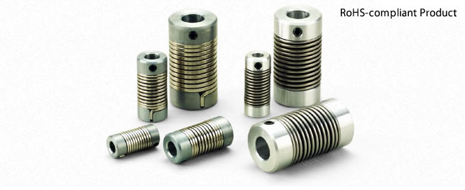
ZG Models
Specifications
| Model | Torque | Misalignment | Max. rotation speed [min-1] | Torsional stiffness [N・m/rad] | Moment of inertia [kg・m2] | Mass [kg] | |||
|---|---|---|---|---|---|---|---|---|---|
| Nominal [N・m] | Max. [N・m] | Parallel [mm] | Angular [°] | Axial [mm] | |||||
| ZG-6 | 0.15 | 0.3 | 0.5 | 5 | ±0.5 | 3000 | 0.17 | 1.95×10⁻⁷ | 0.020 |
| ZG-8 | 0.5 | 1.0 | 1.0 | 8 | ±1.0 | 3000 | 0.48 | 1.02×10⁻⁶ | 0.070 |
| ZG-14 | 1.5 | 3.0 | 1.2 | 8 | ±1.0 | 3000 | 1.70 | 1.15×10⁻⁵ | 0.130 |
*Max. rotation speed does not take into account dynamic balance.
*The moment of inertia and mass are measured for the maximum bore diameter.
Dimensions

| Model | d1, d2 | D | L | L1 | F | M | ||
|---|---|---|---|---|---|---|---|---|
| Pilot bore | Min. | Max. | ||||||
| ZG-6 | 2 | 3 | 6 | 12 | 25 | 9 | 2.4 | M3 |
| ZG-8 | 3 | 4 | 8 | 16 | 35 | 12.5 | 3.5 | M4 |
| ZG-14 | 6 | 7 | 14 | 26 | 50 | 17 | 4.5 | M5 |
*Pilot bores are to be drilled into the part.
*Left and right tap positions may be shifted slightly.
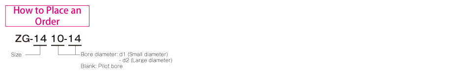
Standard bore diameter
| Model | Standard bore diameter d1, d2 | ||||||||||||
|---|---|---|---|---|---|---|---|---|---|---|---|---|---|
| 3 | 4 | 5 | 6 | 6.35 | 7 | 8 | 9 | 9.525 | 10 | 11 | 12 | 14 | |
| ZG-6 | ● | ● | ● | ● | |||||||||
| ZG-8 | ● | ● | ● | ● | ● | ● | |||||||
| ZG-14 | ● | ● | ● | ● | ● | ● | ● | ● | |||||
*Standard bore-drilled products do not have keyways. Keyways may be possible under some conditions. Contact Miki Pulley for details.
LM Models
Specifications
| Model | Torque | Misalignment | Max. rotation speed [min-1] | Torsional stiffness [N・m/rad] | Moment of inertia [kg・m2] | Mass [kg] | |||
|---|---|---|---|---|---|---|---|---|---|
| Nominal [N・m] | Max. [N・m] | Parallel [mm] | Angular [°] | Axial [mm] | |||||
| LM-6 | 0.5 | 1.0 | 1.0 | 8 | ±1.0 | 6000 | 0.77 | 5.10×10⁻⁷ | 0.020 |
| LM-6-1 | 0.5 | 1.0 | 3.0 | 14 | ±1.5 | 6000 | 0.40 | 7.65×10⁻⁷ | 0.030 |
| LM-9 | 1.0 | 2.0 | 2.5 | 8 | ±1.0 | 6000 | 1.55 | 2.55×10⁻⁶ | 0.050 |
| LM-9-1 | 1.0 | 2.0 | 4.0 | 14 | ±1.5 | 6000 | 0.80 | 3.06×10⁻⁶ | 0.060 |
| LM-14 | 2.0 | 4.0 | 3.0 | 8 | ±1.0 | 6000 | 3.10 | 7.65×10⁻⁶ | 0.090 |
| LM-14-1 | 2.0 | 4.0 | 4.5 | 14 | ±1.5 | 6000 | 1.60 | 9.44×10⁻⁶ | 0.110 |
*Max. rotation speed does not take into account dynamic balance.
*The moment of inertia and mass are measured for the maximum bore diameter.
Dimensions

| Model | d1, d2 | D | L | L1 | L2 | F | M | ||
|---|---|---|---|---|---|---|---|---|---|
| Pilot bore | Min. | Max. | |||||||
| LM-6 | 4 | 5 | 6 | 14 | 35 | 12 | 6.5 | 3.5 | M4 |
| LM-6-1 | 4 | 5 | 6 | 14 | 50 | 12 | 6.5 | 3.5 | M4 |
| LM-9 | 5 | 6 | 9 | 20 | 40 | 14 | 7.5 | 4 | M4 |
| LM-9-1 | 5 | 6 | 9 | 20 | 60 | 14 | 7.5 | 4 | M4 |
| LM-14 | 8 | 9 | 14 | 26 | 50 | 17 | 10 | 5 | M5 |
| LM-14-1 | 8 | 9 | 14 | 26 | 70 | 17 | 10 | 5 | M5 |
*Pilot bores are to be drilled into the part.
*The left and right tap positions are not correlated as shown in the diagram.
Standard bore diameter
| Model | Standard bore diameter d1, d2 | ||||||||||
|---|---|---|---|---|---|---|---|---|---|---|---|
| 5 | 6 | 6.35 | 7 | 8 | 9 | 9.525 | 10 | 11 | 12 | 14 | |
| LM-6(-1) | ● | ● | |||||||||
| LM-9(-1) | ● | ● | ● | ● | ● | ||||||
| LM-14(-1) | ● | ● | ● | ● | ● | ● | |||||
*Standard bore-drilled products do not have keyways. Keyways may be possible under some conditions. Contact Miki Pulley for details.

Standard Hole-drilling Standards
| Models compliant with the old JIS standards (Class 2) | Models compliant with the new JIS standards | Models compliant with the new motor standards | ||||||||||||
|---|---|---|---|---|---|---|---|---|---|---|---|---|---|---|
| Nominal bore diameter | Bore diameter (d1, d2) | Keyway width (W1, W2) | Keyway height (T1, T2) | Set screw hole (M) | Nominal bore diameter | Bore diameter (d1, d2) | Keyway width (W1, W2) | Keyway height (T1, T2) | Set screw hole (M) | Nominal bore diameter | Bore diameter (d1, d2) | Keyway width (W1, W2) | Keyway height (T1, T2) | Set screw hole (M) |
| Tolerance | H7, H8 | E9 | +0.30 | — | Tolerance | H7 | H9 | +0.30 | — | Tolerance | G7 | H9 | +0.30 | — |
| 4 | 4+0.0180 | — | — | 2-M3 | — | — | — | — | — | — | — | — | — | — |
| 5 | 5+0.0180 | — | — | 2-M3 | — | — | — | — | — | — | — | — | — | — |
| 6 | 6+0.0180 | — | — | 2-M4 | — | — | — | — | — | — | — | — | — | — |
| 7 | 7+0.0220 | — | — | 2-M4 | — | — | — | — | — | — | — | — | — | — |
| 8 | 8+0.0220 | — | — | 2-M4 | — | — | — | — | — | — | — | — | — | — |
| 9 | 9+0.0220 | — | — | 2-M4 | — | — | — | — | — | — | — | — | — | — |
| 10 | 10+0.0220 | — | — | 2-M4 | — | — | — | — | — | — | — | — | — | — |
| 11 | 11+0.0180 | — | — | 2-M4 | — | — | — | — | — | — | — | — | — | — |
| 12 | 12+0.0180 | 4+0.050+0.020 | 13.5 | 2-M4 | 12H | 12+0.0180 | 4+0.0300 | 13.8 | 2-M4 | — | — | — | — | — |
| 14 | 14+0.0180 | 5+0.050+0.020 | 16.0 | 2-M4 | 14H | 14+0.0180 | 5+0.0300 | 16.3 | 2-M4 | 14N | 14+0.024+0.006 | 5+0.0300 | 16.3 | 2-M4 |
| 15 | 15+0.0180 | 5+0.050+0.020 | 17.0 | 2-M4 | 15H | 15+0.0180 | 5+0.0300 | 17.3 | 2-M4 | — | — | — | — | — |
| 16 | 16+0.0180 | 5+0.050+0.020 | 18.0 | 2-M4 | 16H | 16+0.0180 | 5+0.0300 | 18.3 | 2-M4 | — | — | — | — | — |
| 17 | 17+0.0180 | 5+0.050+0.020 | 19.0 | 2-M4 | 17H | 17+0.0180 | 5+0.0300 | 19.3 | 2-M4 | — | — | — | — | — |
| 18 | 18+0.0180 | 5+0.050+0.020 | 20.0 | 2-M4 | 18H | 18+0.0180 | 6+0.0300 | 20.8 | 2-M5 | — | — | — | — | — |
| 19 | 19+0.0210 | 5+0.050+0.020 | 21.0 | 2-M4 | 19H | 19+0.0210 | 6+0.0300 | 21.8 | 2-M5 | 19N | 19+0.028+0.007 | 6+0.0300 | 21.8 | 2-M5 |
| 20 | 20+0.0210 | 5+0.050+0.020 | 22.0 | 2-M4 | 20H | 20+0.0210 | 6+0.0300 | 22.8 | 2-M5 | — | — | — | — | — |
| 22 | 22+0.0210 | 7+0.061+0.025 | 25.0 | 2-M6 | 22H | 22+0.0210 | 6+0.0300 | 24.8 | 2-M5 | — | — | — | — | — |
| 24 | 24+0.0210 | 7+0.061+0.025 | 27.0 | 2-M6 | 24H | 24+0.0210 | 8+0.0360 | 27.3 | 2-M6 | 24N | 24+0.028+0.007 | 8+0.0360 | 27.3 | 2-M6 |
| 25 | 25+0.0210 | 7+0.061+0.025 | 28.0 | 2-M6 | 25H | 25+0.0210 | 8+0.0360 | 28.3 | 2-M6 | — | — | — | — | — |
| 28 | 28+0.0210 | 7+0.061+0.025 | 31.0 | 2-M6 | 28H | 28+0.0210 | 8+0.0360 | 31.3 | 2-M6 | 28N | 28+0.028+0.007 | 8+0.0360 | 31.3 | 2-M6 |
| 30 | 30+0.0210 | 7+0.061+0.025 | 33.0 | 2-M6 | 30H | 30+0.0210 | 8+0.0360 | 33.3 | 2-M6 | — | — | — | — | — |
| 32 | 32+0.0250 | 10+0.061+0.025 | 35.5 | 2-M8 | 32H | 32+0.0250 | 10+0.0360 | 35.3 | 2-M8 | — | — | — | — | — |
| 35 | 35+0.0250 | 10+0.061+0.025 | 38.5 | 2-M8 | 35H | 35+0.0250 | 10+0.0360 | 38.3 | 2-M8 | — | — | — | — | — |
*The ø11 or below requirement under the new JIS standards and ø11 requirement for the new motor standards are the same as the old JIS standards (class 2)


