Miki Pulley 102 Models (micro clutches)
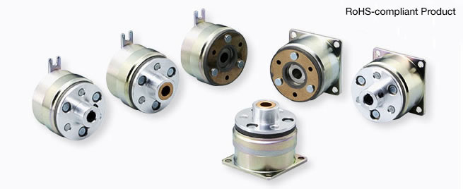
102-□-1□ Types
Specifications
| Model | Size | Dynamic friction torque Td [N・m] | Coil (at 20℃) | Heat resistance class | Max. rotation speed [min-1] | Rotating part moment of inertia J | Allowable engaging work Eeaℓ [J] | Total work performed until readjustment of the air gap ET [J] | Armature pull-in time ta [s] | Torque rise time tp [s] | Torque extinction time td [s] | Mass [kg] | ||||
|---|---|---|---|---|---|---|---|---|---|---|---|---|---|---|---|---|
| Voltage [V] | Wattage [W] | Current [A] | Resistance [Ω] | Armature [kg・m2] | Rotor [kg・m2] | |||||||||||
| 102-02-13 | 02 | 0.4 | DC24 | 6 | 0.25 | 96 | B | 10000 | 6.75×10⁻⁷ | 2.45×10⁻⁶ | 1500 | 2×10⁶ | 0.009 | 0.019 | 0.017 | 0.075 |
| 102-02-15 | 02 | 0.4 | 24 DC | 6 | 0.25 | 96 | B | 500 | 1.00×10⁻⁶ | 2.45×10⁻⁶ | 1500 | 2×10⁶ | 0.009 | 0.019 | 0.017 | 0.081 |
| 102-02-11 | 02 | 0.4 | 24 DC | 6 | 0.25 | 96 | B | 10000 | 1.00×10⁻⁶ | 2.45×10⁻⁶ | 1500 | 2×10⁶ | 0.009 | 0.019 | 0.017 | 0.079 |
| 102-03-13 | 03 | 0.6 | 24 DC | 6 | 0.25 | 96 | B | 10000 | 1.30×10⁻⁶ | 3.25×10⁻⁶ | 2300 | 3×10⁶ | 0.009 | 0.022 | 0.020 | 0.096 |
| 102-03-15 | 03 | 0.6 | 24 DC | 6 | 0.25 | 96 | B | 500 | 1.95×10⁻⁶ | 3.25×10⁻⁶ | 2300 | 3×10⁶ | 0.009 | 0.022 | 0.020 | 0.105 |
| 102-03-11 | 03 | 0.6 | 24 DC | 6 | 0.25 | 96 | B | 10000 | 1.95×10⁻⁶ | 3.25×10⁻⁶ | 2300 | 3×10⁶ | 0.009 | 0.022 | 0.020 | 0.103 |
| 102-04-13 | 04 | 1.2 | 24 DC | 8 | 0.33 | 72 | B | 10000 | 4.38×10⁻⁶ | 1.41×10⁻⁵ | 4500 | 6×10⁶ | 0.011 | 0.028 | 0.030 | 0.178 |
| 102-04-15 | 04 | 1.2 | 24 DC | 8 | 0.33 | 72 | B | 500 | 6.15×10⁻⁶ | 1.41×10⁻⁵ | 4500 | 6×10⁶ | 0.011 | 0.028 | 0.030 | 0.195 |
| 102-04-11 | 04 | 1.2 | 24 DC | 8 | 0.33 | 72 | B | 10000 | 6.15×10⁻⁶ | 1.41×10⁻⁵ | 4500 | 6×10⁶ | 0.011 | 0.028 | 0.030 | 0.191 |
| 102-05-13 | 05 | 2.4 | 24 DC | 10 | 0.42 | 58 | B | 10000 | 9.08×10⁻⁶ | 3.15×10⁻⁵ | 9000 | 9×10⁶ | 0.012 | 0.031 | 0.040 | 0.310 |
| 102-05-15 | 05 | 2.4 | 24 DC | 10 | 0.42 | 58 | B | 500 | 1.38×10⁻⁵ | 3.15×10⁻⁵ | 9000 | 9×10⁶ | 0.012 | 0.031 | 0.040 | 0.335 |
| 102-05-11 | 05 | 2.4 | 24 DC | 10 | 0.42 | 58 | B | 10000 | 1.38×10⁻⁵ | 3.15×10⁻⁵ | 9000 | 9×10⁶ | 0.012 | 0.031 | 0.040 | 0.325 |
*The dynamic friction torque, Td, is measured at a relative speed of 100 min-1.
*The moment of inertia of a rotating body and mass are measured for the maximum bore diameter.
*Keep supply voltage fluctuation to within 10% of coil voltage.
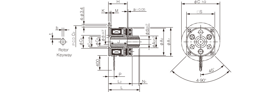
Dimensions

| Size | Radial direction dimensions | Axial direction dimensions | ||||||||||||||||||||
|---|---|---|---|---|---|---|---|---|---|---|---|---|---|---|---|---|---|---|---|---|---|---|
| A1 | A2 | A3 | A4 | C1 | C2 | C3 | C4 | C5 | S | V1 | V2 | V3 | Z | H | J | K | L | P | M | a | X | |
| 02 | 31 | 28 | 19.5 | 10.5 | 39 | 33.5 | 11.4 | 11 | 8 | - | 2-2.1 | 2-5.3 | 2-4 | 4-90° | 18 | 16.5 | 1.5 | 20.5 | 5 | 1.1 | 0.1 | 0.8 |
| 03 | 34 | 32 | 23 | 12.5 | 45 | 38 | 13.6 | 13 | 10 | 33 | 3-2.6 | 3-6 | 3-4.5 | 6-60° | 22.2 | 20.2 | 2 | 24.5 | 6.7 | 1.3 | 0.15 | 1.2 |
| 04 | 43 | 40 | 30 | 18.5 | 54 | 47 | 20 | 19 | 15.5 | 41 | 3-3.1 | 3-6 | 3-5 | 6-60° | 25.4 | 23.4 | 2 | 28.2 | 7 | 1.3 | 0.15 | 1.5 |
| 05 | 54 | 50 | 38 | 25.5 | 65 | 58 | 27.2 | 26 | 22 | 51 | 3-3.1 | 3-6.5 | 3-5.5 | 6-60° | 28.1 | 26.1 | 2 | 31.3 | 8.2 | 1.5 | 0.2 | 1.5 |
*Size 02 is a rounded flange.
*The rotor of size 02 has no keyway. Lock it in place by press-fitting it onto the shaft or the like.
| Size | Shaft bore dimensions | ||||
|---|---|---|---|---|---|
| d1 H7 | Models compliant with the new JIS standards | Models compliant with the old JIS standards | |||
| b P9 | t | b P9 | t | ||
| 02 | 5 | - | - | - | - |
| 03 | 6 | 2-0.006-0.031 | 0.8+0.30 | - | - |
| 04 | 8 | 2-0.006-0.031 | 0.8+0.30 | - | - |
| 10 | 3-0.006-0.031 | 1.2+0.30 | 4+0.050+0.020 | 1.5+0.50 | |
| 05 | 10 | 3-0.006-0.031 | 1.2+0.30 | 4+0.050+0.020 | 1.5+0.50 |
| 15 | 5-0.012-0.042 | 2+0.50 | 5+0.050+0.020 | 2+0.50 | |

Dimensions
| Size | Radial direction dimensions | Axial direction dimensions | ||||||||||||||||
|---|---|---|---|---|---|---|---|---|---|---|---|---|---|---|---|---|---|---|
| A1 | A2 | A3 | C1 | C2 | C3 | C4 | C5 | S | H | J | K | L1 | L2 | M | P | N1 | a | |
| 02 | 31 | 28 | 13 | 39 | 33.5 | 11.4 | 11 | 8 | - | 18 | 16.5 | 1.5 | 27.5 | 22.4 | 1.1 | 5 | 4.8 | 0.1 |
| 03 | 34 | 32 | 14 | 45 | 38 | 13.6 | 13 | 10 | 33 | 22.2 | 20.2 | 2 | 34.5 | 26.5 | 1.3 | 6.7 | 7.8 | 0.15 |
| 04 | 43 | 40 | 18 | 54 | 47 | 20 | 19 | 15.5 | 41 | 25.4 | 23.4 | 2 | 40.2 | 30.8 | 1.3 | 7 | 9.1 | 0.15 |
| 05 | 54 | 50 | 28 | 65 | 58 | 27.2 | 26 | 22 | 51 | 28.1 | 26.1 | 2 | 43.3 | 34.3 | 1.5 | 8.2 | 8.8 | 0.2 |
*Size 02 is a rounded flange.
*The rotor of size 02 has no keyway. Lock it in place by press-fitting it onto the shaft or the like.
| Size | Shaft bore dimensions | |||||
|---|---|---|---|---|---|---|
| d1 H7 | d2 H7 | Models compliant with the new JIS standards | Models compliant with the old JIS standards | |||
| b P9 | t | b P9 | t | |||
| 02 | 5 | 5 | - | - | - | - |
| 03 | 6 | 6 | 2-0.006-0.031 | 0.8+0.30 | - | - |
| 04 | 8 | 8 | 2-0.006-0.031 | 0.8+0.30 | - | - |
| 10 | 10 | 3-0.006-0.031 | 1.2+0.30 | 4+0.050+0.020 | 1.5+0.50 | |
| 05 | 10 | 10 | 3-0.006-0.031 | 1.2+0.30 | 4+0.050+0.020 | 1.5+0.50 |
| 15 | 15 | 5-0.012-0.042 | 2+0.50 | 5+0.050+0.020 | 2+0.50 | |
*The armature type-5 bore d2 is a straight bore.
Dimensions
| Size | Radial direction dimensions | Axial direction dimensions | ||||||||||||||||||
|---|---|---|---|---|---|---|---|---|---|---|---|---|---|---|---|---|---|---|---|---|
| A1 | A2 | A3 | C1 | C2 | C3 | C4 | C5 | S | m | H | J | K | L1 | L2 | M | P | U | T | a | |
| 02 | 31 | 28 | 9.5 | 39 | 33.5 | 11.4 | 11 | 8 | - | M3 | 18 | 16.5 | 1.5 | 27.5 | 22.5 | 1.1 | 5 | 7 | 2.5 | 0.1 |
| 03 | 34 | 32 | 12 | 45 | 38 | 13.6 | 13 | 10 | 33 | 2-M3 | 22.2 | 20.2 | 2 | 34.5 | 26.5 | 1.3 | 6.7 | 10 | 4 | 0.15 |
| 04 | 43 | 40 | 17 | 54 | 47 | 20 | 19 | 15.5 | 41 | 2-M3 | 25.4 | 23.4 | 2 | 40.2 | 30.8 | 1.3 | 7 | 12 | 5 | 0.15 |
| 05 | 54 | 50 | 24 | 65 | 58 | 27.2 | 26 | 22 | 51 | 2-M4 | 28.1 | 26.1 | 2 | 43.3 | 34.3 | 1.5 | 8.2 | 12 | 5 | 0.2 |
*Size 02 is a rounded flange.
*The rotor of size 02 has no keyway. Lock it in place by press-fitting it onto the shaft or the like.
| Size | Shaft bore dimensions | |||||
|---|---|---|---|---|---|---|
| d1 H7 | d2 H7 | Models compliant with the new JIS standards | Models compliant with the old JIS standards | |||
| b P9 | t | b P9 | t | |||
| 02 | 5 | 5 | - | - | - | - |
| 03 | 6 | 6 | 2-0.006-0.031 | 0.8+0.30 | - | - |
| 04 | 8 | 8 | 2-0.006-0.031 | 0.8+0.30 | - | - |
| 10 | 10 | 3-0.006-0.031 | 1.2+0.30 | 4+0.050+0.020 | 1.5+0.50 | |
| 05 | 10 | 10 | 3-0.006-0.031 | 1.2+0.30 | 4+0.050+0.020 | 1.5+0.50 |
| 15 | 15 | 5-0.012-0.042 | 2+0.50 | 5+0.050+0.020 | 2+0.50 | |

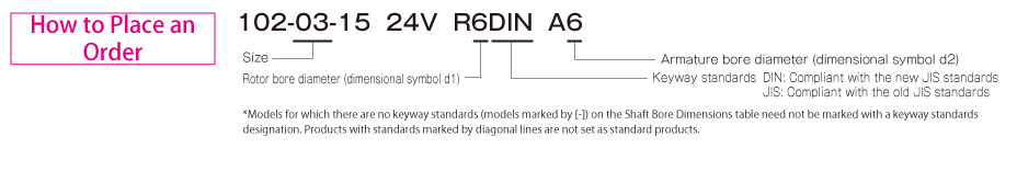
102-□-3□ Types
| Model | Size | Dynamic friction torque Td [N・m] | Coil (at 20℃) | Heat resistance class | Max. rotation speed [min-1] | Rotating part moment of inertia J | Allowable engaging energy Eeaℓ [J] | Total work performed until readjustment of the air gap ET [J] | Armature suction time ta [s] | Torque rise time tp [s] | Torque extinction time td [s] | Mass [kg] | ||||
|---|---|---|---|---|---|---|---|---|---|---|---|---|---|---|---|---|
| Voltage [V] |
Wattage [W] |
Current [A] |
Resistance [Ω] |
Armature [kg・m2] |
Rotor [kg・m2] |
|||||||||||
| 102-02-33 | 02 | 0.4 | 24 DC | 6 | 0.25 | 96 | B | 500 | 6.75×10⁻⁷ | 2.75×10⁻⁶ | 1500 | 2×10⁶ | 0.009 | 0.019 | 0.017 | 0.076 |
| 102-02-35 | 02 | 0.4 | 24 DC | 6 | 0.25 | 96 | B | 500 | 1.00×10⁻⁶ | 2.75×10⁻⁶ | 1500 | 2×10⁶ | 0.009 | 0.019 | 0.017 | 0.082 |
| 102-02-31 | 02 | 0.4 | 24 DC | 6 | 0.25 | 96 | B | 500 | 1.00×10⁻⁶ | 2.75×10⁻⁶ | 1500 | 2×10⁶ | 0.009 | 0.019 | 0.017 | 0.080 |
| 102-03-33 | 03 | 0.6 | 24 DC | 6 | 0.25 | 96 | B | 500 | 1.30×10⁻⁶ | 4.08×10⁻⁶ | 2300 | 3×10⁶ | 0.009 | 0.022 | 0.020 | 0.101 |
| 102-03-35 | 03 | 0.6 | 24 DC | 6 | 0.25 | 96 | B | 500 | 1.95×10⁻⁶ | 4.08×10⁻⁶ | 2300 | 3×10⁶ | 0.009 | 0.022 | 0.020 | 0.110 |
| 102-03-31 | 03 | 0.6 | 24 DC | 6 | 0.25 | 96 | B | 500 | 1.95×10⁻⁶ | 4.08×10⁻⁶ | 2300 | 3×10⁶ | 0.009 | 0.022 | 0.020 | 0.108 |
| 102-04-33 | 04 | 1.2 | 24 DC | 8 | 0.33 | 72 | B | 500 | 4.38×10⁻⁶ | 1.44×10⁻⁵ | 4500 | 6×10⁶ | 0.011 | 0.028 | 0.030 | 0.183 |
| 102-04-35 | 04 | 1.2 | 24 DC | 8 | 0.33 | 72 | B | 500 | 6.15×10⁻⁶ | 1.44×10⁻⁵ | 4500 | 6×10⁶ | 0.011 | 0.028 | 0.030 | 0.200 |
| 102-04-31 | 04 | 1.2 | 24 DC | 8 | 0.33 | 72 | B | 500 | 6.15×10⁻⁶ | 1.44×10⁻⁵ | 4500 | 6×10⁶ | 0.011 | 0.028 | 0.030 | 0.196 |
| 102-05-33 | 05 | 2.4 | 24 DC | 10 | 0.42 | 58 | B | 500 | 9.08×10⁻⁶ | 2.90×10⁻⁵ | 9000 | 9×10⁶ | 0.012 | 0.031 | 0.040 | 0.321 |
| 102-05-35 | 05 | 2.4 | 24 DC | 10 | 0.42 | 58 | B | 500 | 1.38×10⁻⁵ | 2.90×10⁻⁵ | 9000 | 9×10⁶ | 0.012 | 0.031 | 0.040 | 0.346 |
| 102-05-31 | 05 | 2.4 | 24 DC | 10 | 0.42 | 58 | B | 500 | 1.38×10⁻⁵ | 2.90×10⁻⁵ | 9000 | 9×10⁶ | 0.012 | 0.031 | 0.040 | 0.336 |
*The dynamic friction torque, Td, is measured at a relative speed of 100 min-1.
*The moment of inertia of a rotating body and mass are measured for the maximum bore diameter.
*Keep supply voltage fluctuation to within 10% of coil voltage.
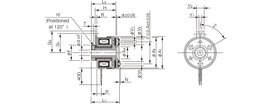
Dimensinos
| Size | Radial direction dimensions | Axial direction dimensions | ||||||||||||||||||||
|---|---|---|---|---|---|---|---|---|---|---|---|---|---|---|---|---|---|---|---|---|---|---|
| A1 | A2 | A3 | A4 | F | V1 | V2 | V3 | G1 | G2 | Y1 | Y2 | Z | m | H | R | L1 | L2 | P | N | T | a | |
| 02 | 31 | 28 | 19.5 | 10.5 | 14 | 2-2.1 | 2-5.3 | 2-4 | 16.8 | 20 | 3.1 | 8 | 4-90° | 2-M3 | 19.5 | 1.6 | 25.9 | 23.5 | 5 | 0.8 | 2.5 | 0.1 |
| 03 | 34 | 32 | 23 | 12.5 | 16 | 3-2.6 | 3-6 | 3-4.5 | 20 | 23 | 3.1 | 8 | 6-60° | 2-M3 | 21.9 | 1.6 | 28.5 | 26.2 | 4.7 | 1.2 | 2.3 | 0.15 |
| 04 | 43 | 40 | 30 | 18.5 | 22 | 3-3.1 | 3-6 | 3-5 | 23 | 26 | 3.1 | 8 | 6-60° | 2-M4 | 25.1 | 1.6 | 33.2 | 30.4 | 5 | 1.5 | 2.8 | 0.15 |
| 05 | 54 | 50 | 38 | 25.5 | 30 | 3-3.1 | 3-6.5 | 3-5.5 | 28 | 31 | 3.1 | 8 | 6-60° | 2-M5 | 27.9 | 1.6 | 37.3 | 34.1 | 6 | 1.5 | 3.3 | 0.2 |
| Size | Shaft bore dimensions |
|---|---|
| d1 H7 | |
| 02 | 5 |
| 03 | 6 |
| 04 | 8 |
| 10 | |
| 05 | 10 |
| 15 |

Dimensions

| Size | Radial direction dimensions | Axial direction dimensions | ||||||||||||||||
|---|---|---|---|---|---|---|---|---|---|---|---|---|---|---|---|---|---|---|
| A1 | A2 | A3 | F | G1 | G2 | Y1 | Y2 | m | H1 | H2 | R | L1 | L2 | P | N | T | a | |
| 02 | 31 | 28 | 13 | 14 | 16.8 | 20 | 3.1 | 8 | 2-M3 | 23.5 | 19.5 | 1.6 | 33 | 27.9 | 5 | 4.8 | 2.5 | 0.1 |
| 03 | 34 | 32 | 14 | 16 | 20 | 23 | 3.1 | 8 | 2-M3 | 26.2 | 21.9 | 1.6 | 38.5 | 30.5 | 4.7 | 7.8 | 2.3 | 0.15 |
| 04 | 43 | 40 | 18 | 22 | 23 | 26 | 3.1 | 8 | 2-M4 | 30.4 | 25.1 | 1.6 | 45.2 | 35.8 | 5 | 9.1 | 2.8 | 0.15 |
| 05 | 54 | 50 | 28 | 30 | 28 | 31 | 3.1 | 8 | 2-M5 | 34.1 | 27.9 | 1.6 | 49.3 | 0.3 | 6 | 8.8 | 3.3 | 0.2 |
| Size | Shaft bore dimensions | |
|---|---|---|
| d1 H7 | d2 H7 | |
| 02 | 5 | 5 |
| 03 | 6 | 6 |
| 04 | 8 | 8 |
| 10 | 10 | |
| 05 | 10 | 10 |
| 15 | 15 | |

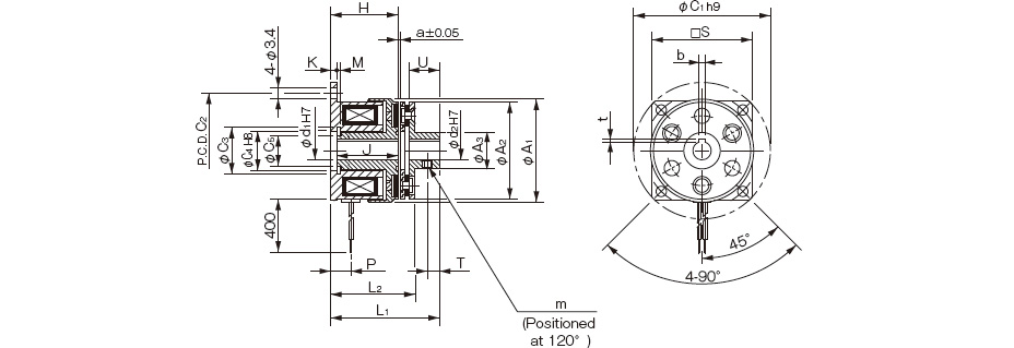
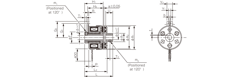
Dimensions
| Size | Radial direction dimensions | Axial direction dimensions | ||||||||||||||||||
|---|---|---|---|---|---|---|---|---|---|---|---|---|---|---|---|---|---|---|---|---|
| A1 | A2 | A3 | F | G1 | G2 | Y1 | Y2 | m1 | m2 | H1 | H2 | R | L1 | L2 | P | U | T1 | T2 | a | |
| 02 | 31 | 28 | 9.5 | 14 | 16.8 | 20 | 3.1 | 8 | 2-M3 | M3 | 23.5 | 19.5 | 1.6 | 33 | 27.9 | 5 | 7 | 2.5 | 2.5 | 0.1 |
| 03 | 34 | 32 | 12 | 16 | 20 | 23 | 3.1 | 8 | 2-M3 | 2-M3 | 26.2 | 21.9 | 1.6 | 38.5 | 30.5 | 4.7 | 10 | 2.3 | 4 | 0.15 |
| 04 | 43 | 40 | 17 | 22 | 23 | 26 | 3.1 | 8 | 2-M4 | 2-M3 | 30.4 | 25.1 | 1.6 | 45.2 | 35.8 | 5 | 12 | 2.8 | 5 | 0.15 |
| 05 | 54 | 50 | 24 | 30 | 28 | 31 | 3.1 | 8 | 2-M5 | 2-M4 | 34.1 | 27.9 | 1.6 | 49.3 | 40.3 | 6 | 12 | 3.3 | 5 | 0.2 |
| Size | Shaft bore dimensions | |||||
|---|---|---|---|---|---|---|
| d1 H7 | d2 H7 | Models compliant with the new JIS standards | Models compliant with the old JIS standards | |||
| b P9 | t | b P9 | t | |||
| 02 | 5 | 5 | - | - | - | - |
| 03 | 6 | 6 | 2-0.006-0.031 | 0.8+0.30 | - | - |
| 04 | 8 | 8 | 2-0.006-0.031 | 0.8+0.30 | - | - |
| 10 | 10 | 3-0.006-0.031 | 1.2+0.30 | 4+0.050+0.020 | 1.5+0.50 | |
| 05 | 10 | 10 | 3-0.006-0.031 | 1.2+0.30 | 4+0.050+0.020 | 1.5+0.50 |
| 15 | 15 | 5-0.012-0.042 | 2+0.50 | 5+0.050+0.020 | 2+0.50 | |