

Miki Pulley CYT Models (Custom micro clutches)

Specifications
| Model | Size | Dynamic friction torque Td [N・m] | Coil (at 20℃) | Heat resistance class | Max. rotation speed [min-1] | Rotating part moment of inertia | Allowable engaging energy Eeaℓ [J] | Total work ET [J] | Armature pull-in time ta [s] | Torque rise time tp [s] | Torque extinction time td [s] | Mass [kg] | ||||
|---|---|---|---|---|---|---|---|---|---|---|---|---|---|---|---|---|
| Voltage [V] | Wattage [W] | Current [A] | Resistance [Ω] | Armature [kg・m2] | Rotor [kg・m2] | |||||||||||
| CYT-025-33B | 025 | 0.4 | 24 DC | 4.5 | 0.188 | 128 | B | 3600 | 1.00×10⁻⁶ | 1.43×10⁻⁶ | 800 | 1.0×10⁶ | 0.014 | 0.028 | 0.030 | 0.07 |
| CYT-03-33B | 03 | 0.5 | 24 DC | 5.5 | 0.23 | 105 | B | 3600 | 1.30×10⁻⁶ | 1.85×10⁻⁶ | 900 | 1.5×10⁶ | 0.015 | 0.030 | 0.040 | 0.13 |
| CYT-03-33M | 03 | 0.5 | 24 DC | 5.5 | 0.23 | 105 | B | 500 | 1.30×10⁻⁶ | 1.90×10⁻⁶ | 900 | 1.5×10⁶ | 0.015 | 0.030 | 0.040 | 0.11 |
| CYT-04-33B | 04 | 1.0 | 24 DC | 5.9 | 0.25 | 98 | B | 3600 | 5.15×10⁻⁶ | 1.00×10⁻⁵ | 1900 | 2.0×10⁶ | 0.030 | 0.040 | 0.040 | 0.26 |
| CYT-04-33M | 04 | 1.0 | 24 DC | 5.9 | 0.25 | 98 | B | 500 | 5.15×10⁻⁶ | 1.05×10⁻⁵ | 1900 | 2.0×10⁶ | 0.030 | 0.040 | 0.040 | 0.23 |
*The dynamic friction torque, Td, is measured at a relative speed of 100 min-1.
*The rotating part moment of inertia and mass are measured for the maximum bore diameter.
*Keep supply voltage fluctuation to within 10% of coil voltage. Also, be careful that energization does not exceed 50%.
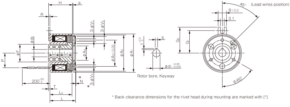
Dimensions

| Size | Radial direction dimensions | Axial direction dimensions | ||||||||||||||||||
|---|---|---|---|---|---|---|---|---|---|---|---|---|---|---|---|---|---|---|---|---|
| d | A1 | A2 | A3 | A4 | F | V1 | V2 | V3 | G1 | G2 | m | H | R | L1 | L2 | P | N | T | a | |
| 03 | 6 | 34 | 32 | 23 | 12.5 | 14 | 3 to 2.6 | 3 to 5.5 | 3 to 6 | 20 | 23 | M3 | 21 | 1.2 | 28.6 | 26.2 | 13 | 3 | 2.3 | 0.2±0.05 |
| 8 | ||||||||||||||||||||
| 04 | 8 | 45 | 42 | 30 | 18.5 | 18 | 3 to 3.1 | 3 to 6 | 3 to 6 | 25 | 27.5 | M4 | 25.3 | 1.2 | 35.1 | 32.4 | 17.5 | 3.5 | 3 | 0.2+0.05-0.1 |
| 10 | ||||||||||||||||||||
* Dimensional symbols N and V3 indicate the clearance dimensions for the rivet head during mounting.

Dimensions CYT-025-33B
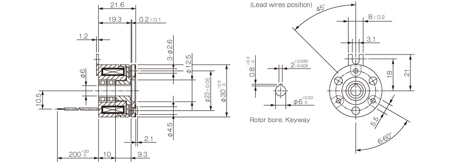

Dimensions
| Size | Nominal diameter | Radial direction dimensions | Axial direction dimensions | Shaft bore dimensions | |||||||||||||||||||||
|---|---|---|---|---|---|---|---|---|---|---|---|---|---|---|---|---|---|---|---|---|---|---|---|---|---|
| A1 | A2 | A3 | A4 | F | V1 | V2 | V3 | G1 | G2 | H | R | L1 | L2 | L3 | L4 | P | N | T | a | d2 | d1 | b | t | ||
| 03 | 6 | 34 | 32 | 23 | 12.5 | 15 | 3 to 2.6 | 3 to 5.5 | 3 to 6 | 20 | 23 | 21 | 1.2 | 22.2 | 19.8 | 10 | 11.3 | 13 | 3 | 1.5 | 0.2±0.05 | 6 | 6 | 2+0.030-0.005 | 0.8+0.30 |
| 8 | 34 | 32 | 23 | 12.5 | 16 | 3 to 2.6 | 3 to 5.5 | 3 to 6 | 20 | 23 | 21 | 1.2 | 22.2 | 19.8 | 10 | 11.3 | 13 | 3 | 1.5 | 0.2±0.05 | 8 | 8 | 2+0.030-0.005 | 0.8+0.30 | |
| 04 | 8 | 45 | 42 | 30 | 18.5 | 19 | 3 to 3.1 | 3 to 6 | 3 to 6 | 25 | 28 | 25.3 | 1.2 | 26.8 | 24.1 | 12 | 13 | 17.5 | 3.5 | 0.9 | 0.2+0.05-0.1 | 8 | 8 | 2+0.030-0.005 | 0.8+0.30 |
| 10 | 45 | 42 | 30 | 18.5 | 19 | 3 to 3.1 | 3 to 6 | 3 to 6 | 25 | 28 | 25.3 | 1.2 | 26.8 | 24.1 | 14 | 11 | 17.5 | 3.5 | 0.9 | 0.2+0.05-0.1 | 10 | 10 | 3+0.025-0 | 1.2+0.30 | |
*Dimensional symbols N and V3 indicate the clearance dimensions for the rivet head during mounting.


