Miki Pulley 112 Models (Micro brakes)

Specifications
| Model | Size | Dynamic friction torque Td [N・m] | Coil (at 20℃) | Heat resistance class | Max. rotation speed [min-1] | Armature moment of inertia J [kg・m2] | Allowable engaging energy Eeaℓ [J] | Total work performed until readjustment of the air gap ET [J] | Armature pull-in time ta [s] | Torque build-up time tp [s] | Torque decaying time td [s] | Mass [kg] | |||
|---|---|---|---|---|---|---|---|---|---|---|---|---|---|---|---|
| Voltage [V] | Wattage [W] | Current [A] | Resistance [Ω] | ||||||||||||
| 112-02-13 | 2 | 0.4 | 24 DC | 6 | 0.25 | 96 | B | 10000 | 6.75×10⁻⁷ | 1500 | 2×10⁶ | 0.004 | 0.01 | 0.01 | 0.053 |
| 112-02-12 | 2 | 0.4 | 24 DC | 6 | 0.25 | 96 | B | 10000 | 1.00×10⁻⁶ | 1500 | 2×10⁶ | 0.004 | 0.01 | 0.01 | 0.057 |
| 112-02-11 | 2 | 0.4 | 24 DC | 6 | 0.25 | 96 | B | 10000 | 1.00×10⁻⁶ | 1500 | 2×10⁶ | 0.004 | 0.01 | 0.01 | 0.057 |
| 112-03-13 | 3 | 0.6 | 24 DC | 6 | 0.25 | 96 | B | 10000 | 1.30×10⁻⁶ | 2300 | 3×10⁶ | 0.005 | 0.012 | 0.008 | 0.072 |
| 112-03-12 | 3 | 0.6 | 24 DC | 6 | 0.25 | 96 | B | 10000 | 1.95×10⁻⁶ | 2300 | 3×10⁶ | 0.005 | 0.012 | 0.008 | 0.079 |
| 112-03-11 | 3 | 0.6 | 24 DC | 6 | 0.25 | 96 | B | 10000 | 1.95×10⁻⁶ | 2300 | 3×10⁶ | 0.005 | 0.012 | 0.008 | 0.079 |
| 112-04-13 | 4 | 1.2 | 24 DC | 8 | 0.33 | 72 | B | 10000 | 4.38×10⁻⁶ | 4500 | 6×10⁶ | 0.007 | 0.016 | 0.01 | 0.118 |
| 112-04-12 | 4 | 1.2 | 24 DC | 8 | 0.33 | 72 | B | 10000 | 6.15×10⁻⁶ | 4500 | 6×10⁶ | 0.007 | 0.016 | 0.01 | 0.131 |
| 112-04-11 | 4 | 1.2 | 24 DC | 8 | 0.33 | 72 | B | 10000 | 6.15×10⁻⁶ | 4500 | 6×10⁶ | 0.007 | 0.016 | 0.01 | 0.131 |
| 112-05-13 | 5 | 2.4 | 24 DC | 10 | 0.42 | 58 | B | 10000 | 9.08×10⁻⁶ | 9000 | 9×10⁶ | 0.01 | 0.023 | 0.012 | 0.2 |
| 112-05-12 | 5 | 2.4 | 24 DC | 10 | 0.42 | 58 | B | 10000 | 1.38×10⁻⁵ | 9000 | 9×10⁶ | 0.01 | 0.023 | 0.012 | 0.215 |
| 112-05-11 | 5 | 2.4 | 24 DC | 10 | 0.42 | 58 | B | 10000 | 1.38×10⁻⁵ | 9000 | 9×10⁶ | 0.01 | 0.023 | 0.012 | 0.215 |
*The dynamic friction torque, Td, is measured at a relative speed of 100 min-1.
*The rotating part moment of inertia and mass are measured for the maximum bore diameter.
*Keep supply voltage fluctuation to within 10% of coil voltage.
Dimensions
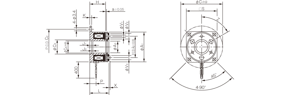
| Size | Radial direction dimensions | Axial direction dimensions | ||||||||||||||||||
|---|---|---|---|---|---|---|---|---|---|---|---|---|---|---|---|---|---|---|---|---|
| A1 | A2 | A3 | C1 | C2 | C3 | C4 | S | V1 | V2 | V3 | Z | H | K | J1 | J2 | L | P | X | a | |
| 02 | 28 | 19.5 | 10.5 | 39 | 33.5 | 11.4 | 11 | – | 2 to 2.1 | 2 to 5.3 | 2 to 4 | 4° to 90° | 13.7 | 1.5 | 2.6 | 1.3 | 16.1 | 5 | 0.8 | 0.1 |
| 03 | 32 | 23 | 12.5 | 45 | 38 | 13.6 | 13 | 33 | 3 to 2.6 | 3 to 6 | 3 to 4.5 | 6° to 60° | 17 | 2 | 3.3 | 1.3 | 19.3 | 6.7 | 1.2 | 0.15 |
| 04 | 40 | 30 | 18.5 | 54 | 47 | 20 | 19 | 41 | 3 to 3.1 | 3 to 6 | 3 to 5 | 6° to 60° | 20 | 2 | 3.3 | 1.3 | 22.8 | 7 | 1.6 | 0.15 |
| 05 | 50 | 38 | 25.5 | 65 | 58 | 27.2 | 26 | 51 | 3 to 3.1 | 3 to 6.5 | 3 to 5.5 | 6° to 60° | 22 | 2 | 3.5 | 1.5 | 25.2 | 8 | 1.6 | 0.2 |
*Size 02 is a rounded flange.

Dimensions
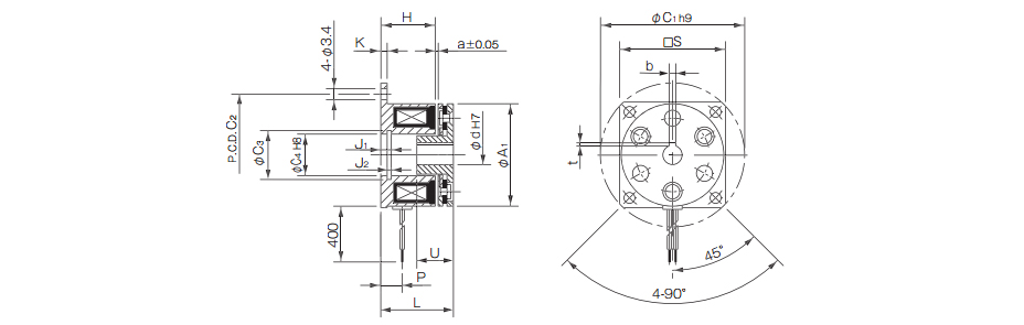
Unit [mm]
| Size | Radial direction dimensions | Axial direction dimensions | ||||||||||||
|---|---|---|---|---|---|---|---|---|---|---|---|---|---|---|
| A1 | C1 | C2 | C3 | C4 | S | H | K | J1 | J2 | L | P | U | a | |
| 02 | 28 | 39 | 33.5 | 11.4 | 11 | - | 13.7 | 1.5 | 2.6 | 1.3 | 18.1 | 5 | 7 | 0.1 |
| 03 | 32 | 45 | 38 | 13.6 | 13 | 33 | 17 | 2 | 3.3 | 1.3 | 21.3 | 6.7 | 10 | 0.15 |
| 04 | 40 | 54 | 47 | 20 | 19 | 41 | 20 | 2 | 3.3 | 1.3 | 25.5 | 7 | 12 | 0.15 |
| 05 | 50 | 65 | 58 | 27.2 | 26 | 51 | 22 | 2 | 3.5 | 1.5 | 28.2 | 8 | 12 | 0.2 |
*Size 02 is a rounded flange.
*The armature hub of size 02 has no keyway. Lock it in place by press-fi tting it onto the shaft or the like.
Unit [mm]
| Size | Shaft bore dimensions | ||||
|---|---|---|---|---|---|
| d1 H7 | Models compliant with the new JIS standards | Models compliant with the old JIS standards | |||
| b P9 | t | b P9 | t | ||
| 02 | 5 | - | - | - | - |
| 03 | 6 | 2-0.006-0.031 | 0.8+0.30 | - | - |
| 04 | 8 | 2-0.006-0.031 | 0.8+0.30 | - | - |
| 10 | 3-0.006-0.031 | 1.2+0.30 | 4+0.050+0.020 | 1.5+0.50 | |
| 05 | 10 | 3-0.006-0.031 | 1.2+0.30 | 4+0.050+0.020 | 1.5+0.50 |
| 15 | 5-0.012-0.042 | 2+0.50 | 5+0.050+0.020 | 2+0.50 | |
Dimensions
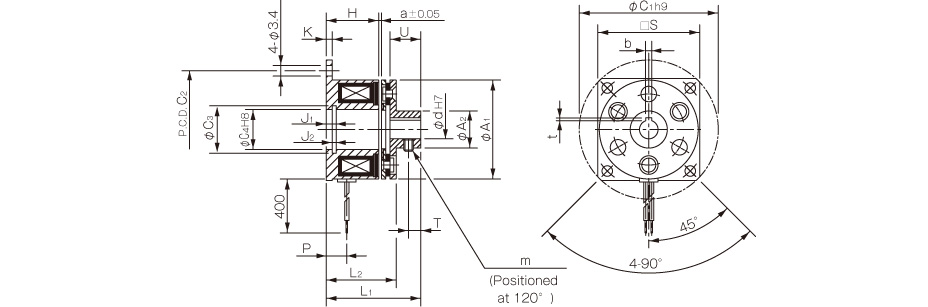
Unit [mm]
| Size | Radial direction dimensions | Axial direction dimensions | ||||||||||||||||
|---|---|---|---|---|---|---|---|---|---|---|---|---|---|---|---|---|---|---|
| A1 | A2 | C1 | C2 | C3 | C4 | S | m | H | K | J1 | J2 | L1 | L2 | P | U | T | a | |
| 02 | 28 | 9.5 | 39 | 33.5 | 11.4 | 11 | - | M3 | 13.7 | 1.5 | 2.6 | 1.3 | 23.1 | 18.1 | 5 | 7 | 2.5 | 0.1 |
| 03 | 32 | 12 | 45 | 38 | 13.6 | 13 | 33 | 2-M3 | 17 | 2 | 3.3 | 1.3 | 29.3 | 21.3 | 6.7 | 10 | 4 | 0.15 |
| 04 | 40 | 17 | 54 | 47 | 20 | 19 | 41 | 2-M3 | 20 | 2 | 3.3 | 1.3 | 34.8 | 25.5 | 7 | 12 | 5 | 0.15 |
| 05 | 50 | 24 | 65 | 58 | 27.2 | 26 | 51 | 2-M4 | 22 | 2 | 3.5 | 1.5 | 37.2 | 28.2 | 8 | 12 | 5 | 0.2 |
*Size 02 is a rounded flange.
Unit [mm]
| Size | Shaft bore dimensions | ||||
|---|---|---|---|---|---|
| d1 H7 | Models compliant with the new JIS standards | Models compliant with the old JIS standards | |||
| b P9 | t | b P9 | t | ||
| 02 | 5 | - | - | - | - |
| 03 | 6 | 2-0.006-0.031 | 0.8+0.30 | - | - |
| 04 | 8 | 2-0.006-0.031 | 0.8+0.30 | - | - |
| 10 | 3-0.006-0.031 | 1.2+0.30 | 4+0.050+0.020 | 1.5+0.50 | |
| 05 | 10 | 3-0.006-0.031 | 1.2+0.30 | 4+0.050+0.020 | 1.5+0.50 |
| 15 | 5-0.012-0.042 | 2+0.50 | 5+0.050+0.020 | 2+0.50 | |