

Miki Pulley 122 Models (Double clutches/brakes)
Specifications
| Model | Size | Dynamic friction torque Td [N・m] | Static friction torque Ts [N・m] | Coil (at 20℃) | Heat resistance class | Max. rotation speed [min-1] | Rotating part moment of inertia J [kg・m2] | Total work performed until readjustment of the air gap ET [J] | Armature pull-in time ta [s] | Torque build-up time tp [s] | Torque decaying time td [s] | Mass [kg] | |||
|---|---|---|---|---|---|---|---|---|---|---|---|---|---|---|---|
| Voltage [V] | Wattage [W] | Current [A] | Resistance [Ω] | ||||||||||||
| 122-06-20G | 06 | 5 | 5.5 | DC24 | 11 | 0.46 | 52 | B | 3000 | 2.19×10⁻⁴ | 36×106 | C: 0.020/B: 0.015 | C: 0.041/B: 0.033 | C: 0.020/B: 0.015 | 4 |
| 122-08-20G | 08 | 10 | 11 | DC24 | 15 | 0.63 | 38 | B | 3000 | 6.55×10⁻⁴ | 60×106 | C: 0.023/B: 0.016 | C: 0.051/B: 0.042 | C: 0.030/B: 0.025 | 6 |
| 122-10-20G | 10 | 20 | 22 | DC24 | 20 | 0.83 | 29 | B | 3000 | 2.12×10⁻³ | 130×106 | C: 0.025/B: 0.018 | C:0.063 / B:0.056 | C: 0.050/B: 0.030 | 9 |
| 122-12-20G | 12 | 40 | 45 | DC24 | 25 | 1.09 | 23 | B | 3000 | 6.35×10⁻³ | 250×106 | C: 0.040/B: 0.027 | C: 0.115/B: 0.090 | C: 0.065/B: 0.050 | 17 |
| 122-16-20G | 16 | 80 | 90 | DC24 | 35 | 1.46 | 16 | B | 3000 | 1.99×10⁻² | 470×106 | C: 0.050/B: 0.035 | C: 0.160/B: 0.127 | C: 0.085/B: 0.055 | 29 |
| 122-20-20G | 20 | 160 | 175 | DC24 | 45 | 1.88 | 13 | B | 2500 | 6.15×10⁻² | 10×108 | C: 0.090/B: 0.065 | C: 0.250/B: 0.200 | C: 0.130/B: 0.070 | 58 |
*The dynamic friction torque, Td, is measured at a relative speed of 100 min-1.
Dimensions
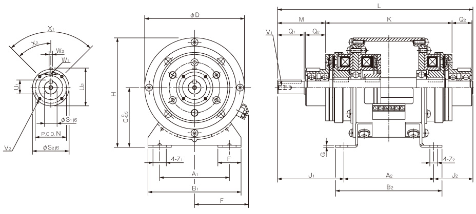
| Size | Dimensions of part | |||||||||||||||||
|---|---|---|---|---|---|---|---|---|---|---|---|---|---|---|---|---|---|---|
| A1 | A2 | B1 | B2 | C | D | E | F | G | H | J1 | J2 | K | L | M | N | Z1 | Z2 | |
| 06 | 65 | 90 | 90 | 105 | 65 | 100 | 27.5 | 61 | 2.6 | 115 | 73 | 48 | 142 | 211 | 47 | 33 | 13.5 | 6.5 |
| 08 | 80 | 110 | 110 | 130 | 80 | 125 | 32.5 | 72 | 3.2 | 142.5 | 83 | 53 | 162 | 246 | 57 | 37 | 15.5 | 9 |
| 10 | 105 | 135 | 140 | 160 | 90 | 150 | 35 | 81 | 3.2 | 165 | 100 | 59 | 190 | 294 | 72 | 47 | 20 | 11.5 |
| 12 | 135 | 160 | 175 | 185 | 112 | 190 | 42.5 | 97 | 4.5 | 207 | 124 | 74 | 222 | 358 | 93 | 52 | 24.5 | 11.5 |
| 16 | 155 | 200 | 200 | 230 | 132 | 230 | 45 | 109 | 6 | 247 | 150.5 | 89.5 | 272 | 440 | 114.5 | 62 | 28 | 14 |
| 20 | 195 | 240 | 240 | 270 | 160 | 290 | 47.5 | 124 | 20 | 305 | 197 | 114 | 348 | 551 | 143 | 74.5 | 28 | 14 |
| Size | Dimensions of shaft | ||||||||||
|---|---|---|---|---|---|---|---|---|---|---|---|
| Q1 | Q2 | S1 | S2 | U1 | U2 | V1 | V2 | X1 | X2 | W1, 2 | |
| 06 | 25 | 20 | 11 | 38 | 12.5 | 39.5 | M4×0.7, length: 8 | 3-M4×0.7, length: 4 | 3° to 120° | 60° | 4 |
| 08 | 30 | 25 | 14 | 45 | 16 | 47 | M4×0.7, length: 8 | 3-M4×0.7, length: 6 | 3° to 120° | 60° | 5 |
| 10 | 40 | 30 | 19 | 55 | 21 | 57 | M6×1, length: 11 | 4-M4×0.7, length: 8 | 4° to 90° | 45° | 5 |
| 12 | 50 | 40 | 24 | 64 | 27 | 67 | M6×1, length: 11 | 4-M4×0.7, length: 8 | 4° to 90° | 45° | 7 |
| 16 | 60 | 50 | 28 | 75 | 31 | 78 | M6×1, length: 11 | 6-M5×0.8, length: 8 | 6° to 60° | 30° | 7 |
| 20 | 80 | 60 | 38 | 90 | 41.5 | 93.5 | M10×1.5, length: 17 | 4-M6×1, length: 12 | 4° to 90° | 45° | 10 |
*The output keyways are old JIS standard class 2 while the key is old JIS standard class 1. Note that the keyway dimensions of the unit hub part do not conform to the old JIS standard. Check them on the dimensions table above.
*When inserting pulleys or the like onto output shafts, use the supplied insertion set.
*The 122-20-20G base is a casting.


