

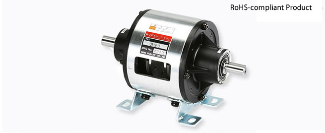
Miki Pulley 125 Models (Clutches and brakes)
125-□-12G
Specifications
| Model | Size | Dynamic friction torque Td [N・m] | Static friction torque Ts [N・m] | Coil (at 20℃) | Heat resistance class | Max. rotation speed [min-1] | Rotating part moment of inertia J [kg・m2] | Total work performed until readjustment of the air gap ET [J] | Armature pull-in time ta [s] | Torque build-up time tp [s] | Torque decaying time td [s] | Mass [kg] | |||
|---|---|---|---|---|---|---|---|---|---|---|---|---|---|---|---|
| Voltage [V] | Wattage [W] | Current [A] | Resistance [Ω] | ||||||||||||
| 125-05-12G | 05 | 2.4 | - | 24 DC | 10 | 0.42 | 58 | B | 3000 | 2.4×10⁻⁵ | 9×10⁶ | C: 0.012/B: 0.010 | C: 0.031/B: 0.023 | C: 0.040/B: 0.012 | 1.2 |
| 125-06-12G | 06 | 5 | 5.5 | 24 DC | 11 | 0.46 | 52 | B | 3000 | 1.28×10⁻⁴ | 36×106 | C: 0.020/B: 0.015 | C: 0.041/B: 0.033 | C: 0.020/B: 0.015 | 2.1 |
| 125-08-12G | 08 | 10 | 11 | 24 DC | 15 | 0.63 | 38 | B | 3000 | 3.70×10⁻⁴ | 60×106 | C: 0.023/B: 0.016 | C: 0.051/B: 0.042 | C: 0.030/B: 0.025 | 4.2 |
| 125-10-12G | 10 | 20 | 22 | 24 DC | 20 | 0.83 | 29 | B | 3000 | 1.40×10⁻³ | 130×106 | C: 0.025/B: 0.018 | C: 0.063/B: 0.056 | C: 0.050/B: 0.030 | 6.8 |
| 125-12-12G | 12 | 40 | 45 | 24 DC | 25 | 1.09 | 23 | B | 3000 | 3.85×10⁻³ | 250×106 | C: 0.040/B: 0.027 | C: 0.115/B: 0.090 | C: 0.065/B: 0.050 | 12 |
| 125-16-12G | 16 | 80 | 90 | 24 DC | 35 | 1.46 | 16 | B | 3000 | 1.35×10⁻² | 470×106 | C: 0.050/B: 0.035 | C: 0.160/B: 0.127 | C: 0.085/B: 0.055 | 22 |
*The dynamic friction torque, Td, is measured at a relative speed of 100 min-1.
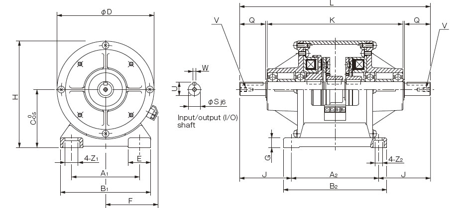
Dimensions 125-05-12G

Dimensions

Unit [mm]
| Size | Dimensions of part | Dimensions of shaft | ||||||||||||||||||
|---|---|---|---|---|---|---|---|---|---|---|---|---|---|---|---|---|---|---|---|---|
| A1 | A2 | B1 | B2 | C | D | E | F | G | H | J | K | L | Z1 | Z2 | Q | S | U | V | W | |
| 06 | 65 | 90 | 90 | 105 | 65 | 100 | 27.5 | 61 | 2.6 | 115 | 48.5 | 132 | 187 | 13.5 | 6.5 | 25 | 11 | 12.5 | M4×0.7, length: 8 | 4 |
| 08 | 80 | 110 | 110 | 130 | 80 | 125 | 32.5 | 72 | 3.2 | 142.5 | 63 | 171 | 236 | 15.5 | 9 | 30 | 14 | 16 | M4×0.7, length: 8 | 5 |
| 10 | 105 | 135 | 140 | 160 | 90 | 150 | 35 | 81 | 3.2 | 165 | 80 | 210 | 295 | 20 | 11.5 | 40 | 19 | 21 | M6×1, length: 11 | 5 |
| 12 | 135 | 160 | 175 | 185 | 112 | 190 | 42.5 | 97 | 4.5 | 207 | 108 | 270 | 376 | 24 | 11 | 50 | 24 | 27 | M6×1, length: 11 | 7 |
| 16 | 155 | 200 | 200 | 230 | 132 | 230 | 45 | 109 | 6 | 247 | 145 | 362 | 490 | 28 | 14 | 60 | 28 | 31 | M6×1, length: 11 | 7 |
*The input/output shaft keyways are old JIS standard class 2 while the key is old JIS standard class 1.
*When inserting pulleys or the like onto input/output shafts, use the supplied insertion set.

125-□-12E,*Made to order
Specifications
| Model | Size | Dynamic friction torque Td [N・m] | Static friction torque Ts [N・m] | Coil (at 20℃) | Heat resistance class | Max. rotation speed [min-1] | Rotating part moment of inertia J [kg・m2] | Total work performed until readjustment of the air gap ET [J] | Armature pull-in time ta [s] | Torque rise time tp [s] | Torque extinction time td [s] | Mass [kg] | |||
|---|---|---|---|---|---|---|---|---|---|---|---|---|---|---|---|
| Voltage [V] | Wattage [W] | Current [A] | Resistance [Ω] | ||||||||||||
| 125-06-12E | 06 | 5 | 5.5 | 24 DC | 11 | 0.46 | 52 | B | 3000 | 1.28×10⁻⁴ | 36×106 | C: 0.020/B: 0.015 | C: 0.041/B: 0.033 | C: 0.020/B: 0.015 | 2.1 |
| 125-08-12E | 08 | 10 | 11 | 24 DC | 15 | 0.63 | 38 | B | 3000 | 3.70×10⁻⁴ | 60×106 | C: 0.023/B: 0.016 | C: 0.051/B: 0.042 | C: 0.030/B: 0.025 | 4.2 |
| 125-10-12E | 10 | 20 | 22 | 24 DC | 20 | 0.83 | 29 | B | 3000 | 1.40×10⁻³ | 130×106 | C: 0.025/B: 0.018 | C: 0.063/B: 0.056 | C: 0.050/B: 0.030 | 6.8 |
| 125-12-12E | 12 | 40 | 45 | 24 DC | 25 | 1.09 | 23 | B | 3000 | 3.85×10⁻³ | 250×106 | C: 0.040/B: 0.027 | C: 0.115/B: 0.090 | C: 0.065/B: 0.050 | 12 |
| 125-16-12E | 16 | 80 | 90 | 24 DC | 35 | 1.46 | 16 | B | 3000 | 1.35×10⁻² | 470×106 | C: 0.050/B: 0.035 | C: 0.160/B: 0.127 | C: 0.085/B: 0.055 | 22 |
*The dynamic friction torque, Td, is measured at a relative speed of 100 min-1.
Dimensions
Unit [mm]
| Size | Dimensions of part | Dimensions of shaft | ||||||||||||||||||
|---|---|---|---|---|---|---|---|---|---|---|---|---|---|---|---|---|---|---|---|---|
| A1 | A2 | B1 | B2 | C | D | E | F | G | H | J | K | L | Z1 | Z2 | Q | S | U | V | W | |
| 06 | 65 | 90 | 90 | 105 | 65 | 100 | 27.5 | 61 | 10 | 115 | 48.5 | 132 | 187 | 13.5 | 6.5 | 25 | 11 | 12.5 | M4×0.7, length: 8 | 4 |
| 08 | 80 | 110 | 110 | 130 | 80 | 125 | 32.5 | 72 | 12 | 142.5 | 63 | 171 | 236 | 15.5 | 9 | 30 | 14 | 16 | M4×0.7, length: 8 | 5 |
| 10 | 105 | 135 | 140 | 160 | 90 | 150 | 35 | 81 | 15 | 165 | 80 | 210 | 295 | 20 | 11.5 | 40 | 19 | 21 | M6×1, length: 11 | 5 |
| 12 | 135 | 160 | 175 | 185 | 112 | 190 | 42.5 | 97 | 15 | 207 | 108 | 270 | 376 | 24.5 | 11 | 50 | 24 | 27 | M6×1, length: 11 | 7 |
| 16 | 155 | 200 | 200 | 230 | 132 | 230 | 45 | 109 | 18 | 247 | 145 | 362 | 490 | 28 | 14 | 60 | 28 | 31 | M6×1, length: 11 | 7 |
| 20 | 195 | 240 | 240 | 270 | 160 | 290 | 47.5 | 124 | 20 | 305 | 188 | 448 | 616 | 28 | 14 | 80 | 38 | 41.5 | M10×1.5, length: 17 | 10 |
*The input/output shaft keyways are old JIS standard class 2 while the key is old JIS standard class 1.
*When inserting pulleys or the like onto input/output shafts, use the supplied insertion set.


