

Miki Pulley 126 Models (Clutch/Brake Units – Motor-coupled Type)

126-□-4B Types
Specifications 1
| Model | Size | Motor output[kW] 4P |
Dynamic friction torque Td [N・m] |
Static friction torque Ts [N・m] |
Coil(at20℃) | Heat resistance class | Rotating part moment of inertia [kg・m2] |
Total work performed until readjustment of the air gap ET [J] |
Armature pull-in time ta[s] |
Torque build-up time tp[s] |
Torque decaying time td[s] |
Mass [kg] |
|||
|---|---|---|---|---|---|---|---|---|---|---|---|---|---|---|---|
| Voltage [V] |
Wattage [W] |
Current [A] |
Resistance [Ω] |
||||||||||||
| 126-06-4B-0.2kW | 06 | 0.2 | 5 | 5.5 | DC24 | 11 | 0.46 | 52 | B | 1.28×10⁻⁴ | 36×106 | C:0.020 B:0.015 |
C:0.041 B:0.033 |
C:0.020 B:0.015 |
8.9 |
| 126-08-4B-0.4kW | 08 | 0.4 | 10 | 11 | DC24 | 15 | 0.63 | 38 | B | 3.70×10⁻⁴ | 60×106 | C:0.023 B:0.016 |
C:0.051 B:0.042 |
C:0.030 B:0.025 |
13 |
| 126-10-4B-0.75kW-IE3 | 10 | 0.75 | 20 | 22 | DC24 | 20 | 0.83 | 29 | B | 1.40×10⁻³ | 130×106 | C:0.025 B:0.018 |
C:0.063 B:0.056 |
C:0.050 B:0.030 |
20 |
| 126-12-4B-1.5kW-IE3 | 12 | 1.5 | 40 | 45 | DC24 | 25 | 1.09 | 23 | B | 3.85×10⁻³ | 250×106 | C:0.040 B:0.027 |
C:0.115 B:0.090 |
C:0.065 B:0.050 |
41 |
| 126-16-4B-2.2kW-IE3 | 16 | 2.2 | 80 | 90 | DC24 | 35 | 1.46 | 16 | B | 1.35×10⁻² | 470×106 | C:0.050 B:0.035 |
C:0.160 B:0.127 |
C:0.085 B:0.055 |
54 |
| 126-16-4B-3.7kW-IE3 | 16 | 3.7 | 80 | 90 | DC24 | 35 | 1.46 | 16 | B | 1.35×10⁻² | 470×106 | C:0.050 B:0.035 |
C:0.160 B:0.127 |
C:0.085 B:0.055 |
69 |
※Totally enclosed fan cooled motors in conformance with JIS C 4210 for 0.2kW・0.4kW motors, and JIS C 4213 for motors over 0.75 kW.
※Motor input power sources are three phase, AC 200V/50Hz、AC200V・AC220V/60Hz.
※Please contact us regarding requests for particular voltages (5 source specification) for general motors, different pole numbers, etc.
※Kinetic friction torque Td values calculated at relative velocity of 100min-1 min.
Specifications 2
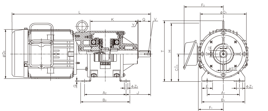
| Model | Dimensions of part | Dimensions of shaft | ||||||||||||||||||||||
|---|---|---|---|---|---|---|---|---|---|---|---|---|---|---|---|---|---|---|---|---|---|---|---|---|
| A1 | A2 | B1 | B2 | C | D1 | D2 | E | F1 | F2 | G | J | K | L | H | T | Y | Z1 | Z2 | Q | S | U | V | W | |
| 126-06-4B-0.2kW | 65 | 90 | 90 | 105 | 65 | 100 | 130 | 27.5 | 61 | - | 2.6 | 48.5 | 102 | 335 | - | - | 3 | 13.5 | 6.5 | 25 | 11 | 12.5 | M4×0.7length8 | 4 |
| 126-08-4B-0.4kW | 80 | 110 | 110 | 130 | 80 | 125 | 145 | 32.5 | 72 | 126.5 | 3.2 | 63 | 127.5 | 389 | 167.5 | - | 2.5 | 15.5 | 9 | 30 | 14 | 16 | M4×0.7length8 | 5 |
| 126-10-4B-0.75kW-IE3 | 105 | 135 | 140 | 160 | 90 | 150 | 163 | 35 | 81 | 136 | 3.2 | 80 | 154 | 462 | 184 | - | 3 | 20 | 11.5 | 40 | 19 | 21 | M6×1length11 | 5 |
| 126-12-4B-1.5kW-IE3 | 135 | 160 | 175 | 185 | 112 | 190 | 182/176 | 42.5 | 97 | 148.5 | 15 | 108 | 194 | 550.5 | - | 244.5 | 3 | 24.5 | 11.5 | 50 | 24 | 27 | M6×1length11 | 7 |
| 126-16-4B-2.2kW-IE3 | 155 | 200 | 200 | 230 | 132 | 230 | 198/195 | 45 | 109 | 155.5 | 18 | 135 | 256 | 649.5 | - | 286 | 4 | 28 | 14 | 50 | 24 | 27 | M6×1length11 | 7 |
| 126-16-4B-3.7kW-IE3 | 155 | 200 | 200 | 230 | 132 | 230 | 225/215 | 45 | 109 | 168.5 | 18 | 145 | 256 | 681 | - | 295 | 4 | 28 | 14 | 60 | 28 | 31 | M6×1length11 | 7 |
※Output shaft keyways are former JIS type 2; keys are former JIS type 1.
※When inserting a pulley into the output shaft, please use the attached insertion set.
※Bases with motor outputs over 1.5 kW are cast metal.
126-□-4F-N Types
Specifications 1
| Model | Size | Motor output [kW] 4P |
Dynamic friction torque Td [N・m] |
Static friction torque Ts [N・m] |
Coil(at20℃) | Heat resistance class | Rotating part moment of inertia [kg・m2] |
Total work performed until readjustment of the air gap ET [J] |
Armature pull-in time ta[s] | Torque build-up time tp[s] |
Torque decaying time td[s] |
Mass [kg] |
|||
|---|---|---|---|---|---|---|---|---|---|---|---|---|---|---|---|
| Voltage [V] |
Wattage [W] |
Current [A] |
Resistance [Ω] |
||||||||||||
| 126-06-4F-N-0.2kW | 06 | 0.2 | 5 | 5.5 | DC24 | 11 | 0.46 | 52 | B | 1.28×10⁻⁴ | 36×106 | C:0.020 B:0.015 |
C:0.041 B:0.033 |
C:0.020 B:0.015 |
8.9 |
| 126-08-4F-N-0.4kW | 08 | 0.4 | 10 | 11 | DC24 | 15 | 0.63 | 38 | B | 3.70×10⁻⁴ | 60×106 | C:0.023 B:0.016 |
C:0.051 B:0.042 |
C:0.030 B:0.025 |
13 |
| 126-10-4F-N-0.75kW-IE3 | 10 | 0.75 | 20 | 22 | DC24 | 20 | 0.83 | 29 | B | 1.40×10⁻³ | 130×106 | C:0.025 B:0.018 |
C:0.063 B:0.056 |
C:0.050 B:0.030 |
20 |
| 126-12-4F-N-1.5kW-IE3 | 12 | 1.5 | 40 | 45 | DC24 | 25 | 1.09 | 23 | B | 3.85×10⁻³ | 250×106 | C:0.040 B:0.027 |
C:0.115 B:0.090 |
C:0.065 B:0.050 |
41 |
| 126-16-4F-N-2.2kW-IE3 | 16 | 2.2 | 80 | 90 | DC24 | 35 | 1.46 | 16 | B | 1.35×10⁻² | 470×106 | C:0.050 B:0.035 |
C:0.160 B:0.127 |
C:0.085 B:0.055 |
54 |
| 126-16-4F-N-3.7kW-IE3 | 16 | 3.7 | 80 | 90 | DC24 | 35 | 1.46 | 16 | B | 1.35×10⁻² | 470×106 | C:0.050 B:0.035 |
C:0.160 B:0.127 |
C:0.085 B:0.055 |
69 |
※Totally enclosed fan cooled motors in conformance with JIS C 4210 for 0.2kW・0.4kW motors, and JIS C 4213 for motors over 0.75 kW.
※Motor input power sources are three phase, AC 200V/50Hz、AC200V・AC220V/60Hz.
※Please contact us regarding requests for particular voltages (5 source specification) for general motors, different pole numbers, etc.
※Kinetic friction torque Td values calculated at relative velocity of 100min-1 min.
Specifications 2

| Model | Dimensions of part | Dimensions of shaft | |||||||||||||||||
|---|---|---|---|---|---|---|---|---|---|---|---|---|---|---|---|---|---|---|---|
| A1 | A2 | D1 | D2 | D3 | D4 | F | G | K | L | T | Y | Z | Q1 | Q2 | S | U | V | W | |
| 126-06-4F-N-0.2kW | 90° | 45° | 160 | 130 | 110 | 130 | - | 8 | 107 | 335 | - | 3.5 | 10 | 23 | 25 | 11 | 12.5 | M4×0.7length8 | 4 |
| 126-08-4F-N-0.4kW | 90° | 45° | 160 | 145 | 110 | 130 | 124 | 10 | 130.5 | 389 | - | 3.5 | 10 | 30 | 30 | 14 | 16 | M4×0.7length8 | 5 |
| 126-10-4F-N-0.75kW-IE3 | 90° | 45° | 200 | 163 | 130 | 165 | 131 | 12 | 157.5 | 463 | - | 3.5 | 12 | 40 | 40 | 19 | 21.5 | M6×1length11 | 6 |
| 126-12-4F-N-1.5kW-IE3 | 90° | 45° | 200 | 182/176 | 130 | 165 | 148.5 | 12 | 197.5 | 551 | 133 | 3.5 | 12 | 50 | 50 | 24 | 27 | M6×1length11 | 8 |
| 126-16-4F-N-2.2kW-IE3 | 90° | 45° | 250 | 198/195 | 180 | 215 | 155.5 | 16 | 260.5 | 660 | 154 | 4 | 15 | 60 | 60 | 28 | 31 | M6×1length11 | 8 |
| 126-16-4F-N-3.7kW-IE3 | 90° | 45° | 250 | 225/215 | 180 | 215 | 168.5 | 16 | 260.5 | 681.5 | 163 | 4 | 15 | 60 | 60 | 28 | 31 | M6×1length11 | 8 |
※Flange and output shaft dimensions are in conformance with IEC、JEM standard flange motors. (Size 06 has keys and keyways)
※When inserting a pulley into the output shaft, please use the attached insertion set.


