

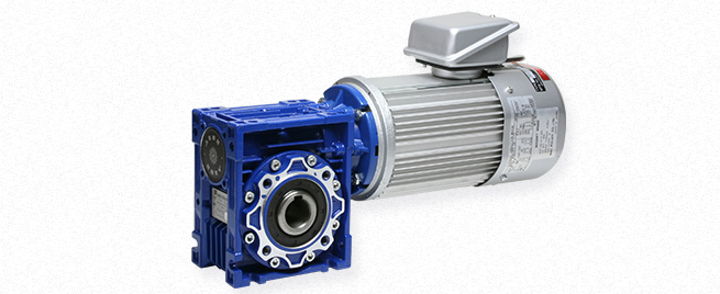
Miki Pulley RWM-BS Types
Specifications 1
| Model | Motor output [kW] |
Poles | Power supply Voltage[V]/Frequency[Hz] | Speed reducer frame number | Speed reduction ratio | Mass [kg] |
|||||
|---|---|---|---|---|---|---|---|---|---|---|---|
| 10 | 20 | 30 | 40 | 50 | 60 | ||||||
| RWM-02BS-40-□ | 0.2 | 4 | 3-phase 200/50、200・220/60 | 40 | 1/10 | 1/20 | 1/30 | 1/40 | 1/50 | 1/60 | 8.3 |
| RWM-04BS-50-□ | 0.4 | 4 | 3-phase 200/50、200・220/60 | 50 | 1/10 | 1/20 | 1/30 | 1/40 | 1/50 | 1/60 | 10.7 |
| RWM-07BS-63N-□-IE3 | 0.75 | 4 | 3-phase 200/50、200・220/60 | 63N | 1/10 | 1/20 | 1/30 | 1/40 | 1/50 | 1/60 | 24 |
| RWM-15BS-75N-□-IE3 | 1.5 | 4 | 3-phase 200/50、200・220/60 | 75N | 1/10 | 1/20 | 1/30 | 1/40 | 1/50 | 1/60 | 32 |
※Totally enclosed fan cooled motors in conformance with JIS C 4210 for 0.2kW・0.4kW motors, and JIS C 4213 for motors over 0.75 kW.
Specifications 2
| Model | Braking method | Brake rated torque [N・m] |
Brake voltage [V] |
Brake current [A] |
Brake heat resistance class |
Rated Brake |
Motor moment of inertia[kg・m2] | Braking delay time[s] | Gap[mm] | Internal brake power source model | ||
|---|---|---|---|---|---|---|---|---|---|---|---|---|
| AC separate switching off | DC separate switching off | Specified | Limit | |||||||||
| RWM-02BS-40-□ | Spring-Actuated | 2 | DC 90 | 0.2 | B | Continuity | 0.58×10⁻³ | 0.1 | 0.03 | 0.2 | 0.5 | BEM-A-62 |
| RWM-04BS-50-□ | Spring-Actuated | 4 | DC 90 | 0.2 | B | Continuity | 0.8×10⁻³ | 0.1 | 0.03 | 0.2 | 0.5 | BEM-A-62 |
| RWM-07BS-63N-□-IE3 | Spring-Actuated | 8 | DC 90 | 0.61 | B | Continuity | 2.3×10⁻³ | 0.15 | 0.05 | 0.2 | 0.5 | BEM-A-64 |
| RWM-15BS-75N-□-IE3 | Spring-Actuated | 15 | DC 90 | 0.61 | B | Continuity | 4.5×10⁻³ | 0.15 | 0.05 | 0.2 | 0.5 | BEM-A-64 |
Specifications 3
| Model | Frequency [Hz] |
Output shaft revolution speed[min-1] and output shaft torque[N・m] in each deceleration ratio | |||||||||||
|---|---|---|---|---|---|---|---|---|---|---|---|---|---|
| 1/10 | 1/20 | 1/30 | 1/40 | 1/50 | 1/60 | ||||||||
| Speed | Torque | Speed | Torque | Speed | Torque | Speed | Torque | Speed | Torque | Speed | Torque | ||
| RWM-02BS-40-□ | 50 | 141.5 | 11.7 | 70.8 | 21.5 | 47.2 | 28.9 | 35.4 | 35.8 | 28.3 | 39 | 23.6 | 36 |
| 60 | 170 | 9.7 | 85 | 17.9 | 56.7 | 24.1 | 42.5 | 29.8 | 34 | 35.5 | 28.3 | 36 | |
| RWM-04BS-50-□ | 50 | 138 | 24.3 | 69 | 44.6 | 46 | 60.9 | 34.5 | 75.6 | 27.6 | 73 | 23 | 68 |
| 60 | 165 | 20.3 | 82.5 | 37.3 | 55 | 51 | 41.3 | 63.2 | 33 | 73 | 27.5 | 68 | |
| RWM-07BS-63N-□-IE3 | 50 | 144 | 45.7 | 72 | 85.1 | 48 | 117 | 36 | 145 | 28.8 | 135 | 24 | 130 |
| 60 | 173 | 38.3 | 86.5 | 71.3 | 57.7 | 97.6 | 43.3 | 123 | 34.6 | 135 | 28.8 | 130 | |
| RWM-15BS-75N-□-IE3 | 50 | 144 | 93.9 | 72 | 177 | 48 | 230 | 36 | 220 | 28.8 | 210 | 24 | 200 |
| 60 | 171.5 | 79.2 | 85.8 | 150 | 57.2 | 211 | 42.9 | 220 | 34.3 | 210 | 28.6 | 200 | |
※Output shaft revolution speed and output shaft torque values calculated at a 200V/50・60Hz rated value load. However, there are instances when output shaft torque is limited by the reducer tolerance.
Dimensions
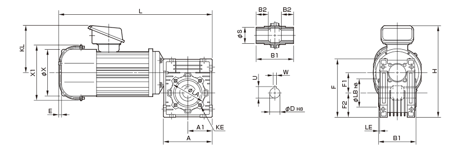
Unit [mm]
| Model | Dimensions of part | Dimensions of Output part | |||||||||||||||||||
|---|---|---|---|---|---|---|---|---|---|---|---|---|---|---|---|---|---|---|---|---|---|
| A | A1 | E | F | F1 | F2 | H | KL | L | X | X1 | KE | LA | LB | LE | S | B1 | B2 | D | U | W | |
| RWM-02BS-40-□ | 100 | 50 | 7 | 121.5 | 40 | 50 | 206 | 116 | 339 | 124 | 137 | 4-M6-8 | 75 | 60 | 2.5 | 30 | 78 | 26 | 18 | 20.8 | 6 |
| RWM-04BS-50-□ | 120 | 60 | 7 | 144 | 50 | 60 | 226 | 116 | 377 | 124 | 137 | 4-M8-9 | 85 | 70 | 2.5 | 40 | 92 | 30 | 25 | 28.3 | 8 |
| RWM-07BS-63N-□-IE3 | 144 | 72 | 5 | 179 | 63 | 72 | 263 | 128 | 486 | 162 | 183 | 8-M8-11 | 95 | 80 | 3 | 45 | 112 | 36 | 25 | 28.3 | 8 |
| RWM-15BS-75N-□-IE3 | 178 | 89 | – | 209 | 75 | 86 | 296 | 135 | 560.5 | 182 | 203 | 8-M8-12 | 115 | 95 | 3 | 50 | 120 | 40 | 28 | 31.3 | 8 |
※Output component tap hole KE dimensions are: quantity-screw designation-screw depth; quantity refers to the quantity on one side.


