

Miki Pulley RWP Models

Specifications 1
| Model | Motor output[kW] | Poles | Power supply Voltage[V]/Frequency[Hz] | Speed reducer frame number | Speed reduction ratio | Mass [kg] |
|||||
|---|---|---|---|---|---|---|---|---|---|---|---|
| 10 | 20 | 30 | 40 | 50 | 60 | ||||||
| RWP-02-□-40-□-IE1 | 0.2 | 4 | 3-phase 200/50、200・220/60 | 40 | 1/10 | 1/20 | 1/30 | 1/40 | 1/50 | 1/60 | 10.7 |
| RWP-04-□-50-□-IE1 | 0.4 | 4 | 3-phase 200/50、200・220/60 | 50 | 1/10 | 1/20 | 1/30 | 1/40 | 1/50 | 1/60 | 15.4 |
| RWP-07-□-63N-□-IE3 | 0.75 | 4 | 3-phase 200/50、200・220/60 | 63N | 1/10 | 1/20 | 1/30 | 1/40 | 1/50 | 1/60 | 27.3 |
| RWP-15-□-75N-□-IE3 | 1.5 | 4 | 3-phase 200/50、200・220/60 | 75N | 1/10 | 1/20 | 1/30 | 1/40 | 1/50 | 1/60 | 39.9 |
※Totally enclosed fan cooled motors in conformance with JIS C 4210 for 0.2kW・0.4kW motors, and JIS C 4213 for motors over 0.75 kW.
Specifications 2
| Model | Frequency [Hz] |
Output shaft revolution speed[min-1] and output shaft torque[N・m] in each deceleration ratio | |||||
|---|---|---|---|---|---|---|---|
| 1/10 | 1/20 | 1/30 | 1/40 | 1/50 | 1/60 | ||
| 50 | 50~200 | 25~100 | 17~68 | 12.5~50 | 10~40 | 8.5~34 | |
| 60 | 60~240 | 30~120 | 20~80 | 15~60 | 12~48 | 10~40 | |
| RWP-02-□-40-□-IE1 | 50 | 14.2~6.7 | 25.2~12.3 | 33.5~17 | 41~20.8 | 45~25.2 | 46~28.8 |
| 60 | 13.6~5.1 | 24.1~9.4 | 32.1~13.1 | 39.4~16.1 | 45~19.5 | 45~22 | |
| RWP-04-□-50-□-IE1 | 50 | 29.2~13.6 | 53.3~25 | 71~35 | 84.4~43.5 | 91~51.2 | 83~57.6 |
| 60 | 26.4~11.2 | 48.8~20.5 | 64.4~28.9 | 79.2~36.4 | 85~42.9 | 80~47.6 | |
| RWP-07-□-63N-□-IE3 | 50 | 55.9~25.8 | 101~48.6 | 130~66.6 | 163~84 | 173~99 | 160~112 |
| 60 | 50.8~20.9 | 91.8~39.4 | 121~54 | 154~69.1 | 168~81.6 | 155~93.6 | |
| RWP-15-□-50N-□-IE3 | 50 | 113~53.9 | 207~103 | 277~141 | 280~181 | 250~190 | 240~180 |
| 60 | 103~44 | 191~86 | 260~116 | 270~148 | 240~170 | 235~160 | |
※Output shaft revolution speed and output shaft torque values calculated at a 200V/50・60Hz rated value load. However, there are instances when output shaft torque is limited by the reducer tolerance.
Dimensions
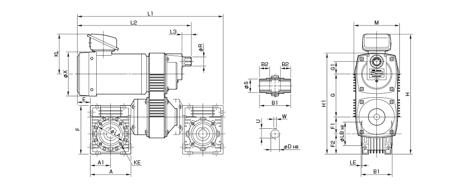
Unit [mm]
| Model | Dimensions of part | Dimensions of Output part | |||||||||||||||||||||||||
|---|---|---|---|---|---|---|---|---|---|---|---|---|---|---|---|---|---|---|---|---|---|---|---|---|---|---|---|
| A | A1 | E | F | F1 | F2 | G | G1 | H | H1 | KL | L1 | L2 | L3 | M | R | X | KE | LA | LB | LE | S | B1 | B2 | D | U | W | |
| RWP-02-□-40-□-IE1 | 100 | 50 | 43 | 121.5 | 40 | 50 | 115 | 35 | 323 | 258 | 118 | 384 | 311 | 28 | 115 | 27 | 131 | 4-M6-8 | 75 | 60 | 2.5 | 30 | 78 | 26 | 18 | 20.8 | 6 |
| RWP-04-□-50-□-IE1 | 120 | 60 | 38.5 | 144 | 50 | 60 | 127 | 37 | 355 | 299 | 118 | 432.5 | 337.5 | 28 | 136 | 27 | 131 | 4-M8-9 | 85 | 70 | 2.5 | 40 | 92 | 30 | 25 | 28.3 | 8 |
| RWP-07-□-63N-□-IE3 | 144 | 72 | 11.5 | 179 | 63 | 72 | 156 | 45 | 419.5 | 367 | 128.5 | 510.5 | 390.5 | 41 | 168 | 37 | 162 | 8-M8-11 | 95 | 80 | 3 | 45 | 112 | 36 | 25 | 28.3 | 8 |
| RWP-15-□-75N-□-IE3 | 178 | 89 | -3 | 209 | 75 | 86 | 176 | 60 | 478 | 427 | 141 | 598 | 450.5 | 41 | 200 | 37 | 187 | 8-M8-12 | 115 | 95 | 3 | 50 | 120 | 40 | 28 | 31.3 | 8 |
※Output component tap hole KE dimensions are: quantity-screw designation-screw depth; quantity refers to the quantity on one side.


