

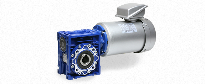
Miki Pulley RWM Models
Specifications 1
| Model | Motor output[kW] | Poles | Power supply Voltage[V]/Frequency[Hz] | Speed reducer frame number | Speed reduction ratio | Mass[kg] | |||||
|---|---|---|---|---|---|---|---|---|---|---|---|
| 10 | 20 | 30 | 40 | 50 | 60 | ||||||
| RWM-02-40-□-IE1 | 0.2 | 4 | 3-phase 200/50、200・220/60 | 40 | 1/10 | 1/20 | 1/30 | 1/40 | 1/50 | 1/60 | 8.8 |
| RWM-04-50-□-IE1 | 0.4 | 4 | 3-phase 200/50、200・220/60 | 50 | 1/10 | 1/20 | 1/30 | 1/40 | 1/50 | 1/60 | 12 |
| RWM-07-63N-□-IE3 | 0.75 | 4 | 3-phase 200/50、200・220/60 | 63N | 1/10 | 1/20 | 1/30 | 1/40 | 1/50 | 1/60 | 23.2 |
| RWM-15-75N-□-IE3 | 1.5 | 4 | 3-phase 200/50、200・220/60 | 75N | 1/10 | 1/20 | 1/30 | 1/40 | 1/50 | 1/60 | 33 |
※Totally enclosed fan cooled motors in conformance with JIS C 4210 for 0.2kW・0.4kW motors, and JIS C 4213 for motors over 0.75 kW.
Specifications 2
| Model | Frequency [Hz] |
Output shaft revolution speed[min-1] and output shaft torque[N・m] in each deceleration ratio | |||||||||||
|---|---|---|---|---|---|---|---|---|---|---|---|---|---|
| 1/10 | 1/20 | 1/30 | 1/40 | 1/50 | 1/60 | ||||||||
| speed | torque | speed | torque | speed | torque | speed | torque | speed | torque | speed | torque | ||
| RWM-02-40-□-IE1 | 50 | 143 | 11.6 | 71.5 | 21.2 | 47.7 | 28.6 | 35.8 | 35.4 | 28.6 | 39 | 23.8 | 36 |
| 60 | 171.5 | 9.6 | 85.8 | 17.7 | 57.2 | 23.8 | 42.9 | 29.5 | 34.3 | 35.2 | 28.6 | 36 | |
| RWM-04-50-□-IE1 | 50 | 142.5 | 23.5 | 71.3 | 43.2 | 47.5 | 59 | 35.6 | 73.2 | 28.5 | 73 | 23.8 | 68 |
| 60 | 171 | 19.6 | 85.5 | 36 | 57 | 49.2 | 42.8 | 61 | 34.2 | 73 | 28.5 | 68 | |
| RWM-07-63N-□-IE3 | 50 | 144 | 44.7 | 72 | 83.3 | 48 | 114 | 36 | 144 | 28.8 | 135 | 24 | 130 |
| 60 | 172.5 | 37.3 | 86.3 | 69.4 | 57.5 | 95.1 | 43.1 | 120 | 34.5 | 135 | 28.8 | 130 | |
| RWM-15-75N-□-IE3 | 50 | 145 | 94.9 | 72.5 | 179 | 48.3 | 230 | 36.3 | 220 | 29 | 210 | 24.2 | 200 |
| 60 | 174 | 79.2 | 87 | 150 | 58 | 211 | 43.5 | 220 | 34.8 | 210 | 29 | 200 | |
※Output shaft revolution speed and output shaft torque values calculated at a 200V/50・60Hz rated value load. However, there are instances when output shaft torque is limited by the reducer tolerance.
Dimensions
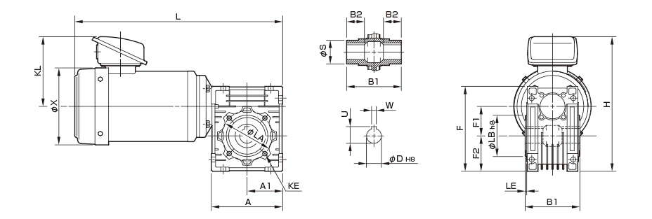
Unit [mm]
| Model | Dimensions of part | Dimensions of output part | |||||||||||||||||
|---|---|---|---|---|---|---|---|---|---|---|---|---|---|---|---|---|---|---|---|
| A | A1 | F | F1 | F2 | H | KL | L | X | KE | LA | LB | LE | S | B1 | B2 | D | U | W | |
| RWM-02-40-□-IE1 | 100 | 50 | 121.5 | 40 | 50 | 208 | 118 | 312.5 | 131 | 4-M6-8 | 75 | 60 | 2.5 | 30 | 78 | 26 | 18 | 20.8 | 6 |
| RWM-04-50-□-IE1 | 120 | 60 | 144 | 50 | 60 | 228 | 118 | 350 | 131 | 4-M8-9 | 85 | 70 | 2.5 | 40 | 92 | 30 | 25 | 28.3 | 8 |
| RWM-07-63N-□-IE3 | 144 | 72 | 179 | 63 | 72 | 263.5 | 128.5 | 414.5 | 162 | 8-M8-11 | 95 | 80 | 3 | 45 | 112 | 36 | 25 | 28.3 | 8 |
| RWM-15-75N-□-IE3 | 178 | 89 | 209 | 75 | 86 | 302 | 141 | 480 | 187 | 8-M8-12 | 115 | 95 | 3 | 50 | 120 | 40 | 28 | 31.3 | 8 |
※Output component tap hole KE dimensions are: quantity-screw designation-screw depth; quantity refers to the quantity on one side.


