

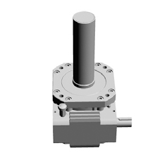
Tsubaki Jack LiniSpeed Jack

The LiniSpeed Jack is an innovative jack that provides high-speed, high-frequency operations and low-floor specifications.
Achieves high speed operation (maximum 200mm/s) and a maximum 100% ED hourly allowable load rate to help boost equipment productivity.
Available in smaller sizes than previous jacks, despite the increased operation speed. In addition, it enables low-floor specifications thanks to its new design to help contribute to more compact equipment.
Model Numbering Example
| SJ | 030 | H | – | TU | T | 4 | M | K2 |
| Series | Frame No. | Speed | Mounting Type | Shaft Arrangement | Stroke | Option | Option |
Frame No. (Allowable thrust)
030: 30kN{3tf}/ 050: 50kN{5tf}
Speed
Max. 200mm/s
Mounting Type
| U Face mount |
S Flange/screw side |
C Flange/cover side |
|
|---|---|---|---|
| T Screw facing up |
TU |
TS Screw compressive load ↓ 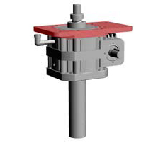 |
TC Screw tensile load ↓  |
| B Screw facing down |
BU 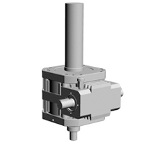 |
BS ↑ ↑Screw compressive load |
BC  ↑ ↑Screw tensile load |
- Position of pressure vent and drain plug varies with mounting position. Screws not facing up or down are made-to-order.
- Specifications that prevent rotation have limited screw shaft speeds. Contact a Tsubaki representative for more information.
- Bellows are MTO products. Please contact a Tsubaki representative as further consideration of shaft speed will be needed. The function of the bellows is to protect the screw from dust, and not to prevent the infiltration of water from the outside.
- Limit screw compressive load/screw tensile load to 50% of allowable thrust.
Shaft Arrangement
| T Dual shafts |
R Right side only |
L Left side only |
|
|---|---|---|---|
| Screw facing up | 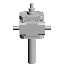 |
 |
 |
| Screw facing down | 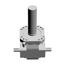 |
 |
 |
Stroke
| mm | |
|---|---|
| 1 | 100 |
| 2 | 200 |
| 3 | 300 |
| 4 | 400 |
| 5 | 500 |
| 6 | 600 |
| 8 | 800 |
| 10 | 1000 |
| 12 | 1200 |
| 15 | 1500 |
- Strokes other than listed above are made-to-order.
Output Option
| Code | Blank | M | I | J |
|---|---|---|---|---|
| Option | 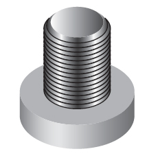 |
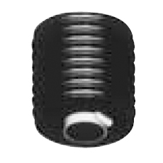 Bellows (MTO items) Bellows (MTO items) |
 I-type end fitting I-type end fitting |
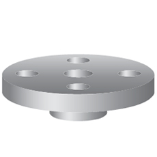 Table type end fitting Table type end fitting |
- Provide option codes in the order above.
Position Sensor Option
| Option | Code |  |
|---|---|---|
| LS Counter (*) | Y | |
| Position detecting unit (*) | ||
| Internal LSx2 | K2 | |
| Internal LSx4 | K4 | |
| Potentiometer | P | |
| Rotary encoder | R | |
- Use LS counter when input rotation speed is below 1800rpm.
- Provide option codes in the order above.


