

Tsubaki Power Cylinder Multi Series
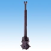
You can choose from the compact and economical type (LPTB) and the thrust detection type with a safety device (LPTC) according to your application’s needs.
Features
Tough Construction
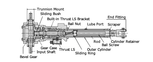
The actuator portion supporting the load and the reducer portion are separated. There is no change in the gear tooth contact due to fluctuating load.
Synchronous Operation
Using the input shaft with enough strength allows synchronous operation of multiple units.
Long Service Life
The ball screw with large load capacity extends its operating life.
Swinging Operation
Since the input shaft and trunnion part have the same shaft center, swinging motion is allowed while linkage operation is performed.
Safety
A thrust detection mechanism can be built-in to detect overload and protect the machine. (LPTC)
Each Protector Use & Structure
TB Type: Basic Type without Overload Protector
This type has no overload protection device. Our Shock Relay is recommended to be used with the Power Cylinder, which can detect electrical overload at the input side and protect the machine.

TC Type: Thrust Detection Unit Type
The thrust detection unit combines two types of pressurized disk springs with different spring constants and a limit switch. It operates effectively in the cases below:
- Press/Pull stopping
- Electrical signal required during overload
- Action of overload from load side during stopping
*The built-in spring unit can absorb deflection shock load.
Reference Number System

*”R” and “L” indicate the relation of the input shaft rotation and the rod movement directions.
*I type end fitting is standard for LPT6000B or above.
Standard Specifications
| Model No. | Allowable Thrust kN(kgf) |
Screw Lead mm |
Gear Ratio | Overall Efficiency % |
No-Load Idling Torque N·cm{kgf·cm} |
|---|---|---|---|---|---|
| LPTB 500B LPTC |
4.90 {500} |
6 | 2 | 85.5 | 0.74 {0.075} |
| LPTB 1000B LPTC |
9.80 {1000} |
8 | 2 | 85.5 | 2.06 {0.21} |
| LPTB 2000B LPTC |
19.6 {2000} |
10 | 2 | 85.5 | 5.19 {0.53} |
| LPTB 4000B LPTC |
39.2 {4000} |
12 | 2 | 85.5 | 14.7 {1.5} |
| LPTB 6000B LPTC |
58.8 {6000} |
12 | 2 | 85.5 | 23.5 {2.4} |
| LPTB 8000B LPTC |
78.4 {8000} |
16 | 2 | 85.5 | 108 {11} |
| LPTB 12000B LPTC |
117 {12000} |
16 | 2 | 85.5 | 160 {16.3} |
| LPTB 16000B LPTC |
156 {16000} |
24 | 2 | 85.5 | 331 {33.8} |
| LPTB 32000B LPTC |
313 {32000} |
24 | 2 | 85.5 | 624 {63.7} |


