

MOM-C

Flexible coupling – Oldham – type – Set screw type
Dimension Drawing


Dimensions/Specifications/CAD
| Part Number | A | L | W | E | F | G | M | Wrench Torque (N・m) |
|---|---|---|---|---|---|---|---|---|
| MOM-15C | 15 | 6.6 | 19 | 6.9 | 2.15 | 5.2 | M1.6 | 0.25 |
| MOM-17C | 17 | 9 | 25 | 7.3 | 2.65 | 5.5 | M2 | 0.5 |
| MOM-20C | 20 | 10 | 28 | 11.1 | 3.25 | 7.25 | M2.5 | 1 |
| MOM-26C | 26 | 11.5 | 31.6 | 13.3 | 4 | 9 | M3 | 1.5 |
| MOM-30C | 30 | 12 | 34 | 15.5 | 4 | 11 | M3 | 1.5 |
| MOM-34C | 34 | 13 | 35 | 17.5 | 4.5 | 12 | M4 | 3.5 |
| MOM-38C | 38 | 15 | 40.5 | 21.5 | 4.75 | 14 | M4 | 3.5 |
| MOM-45C | 45 | 16.2 | 47.6 | 24.3 | 6.2 | 16 | M5 | 8 |
| MOM-55C | 55 | 20.8 | 58.6 | 27.7 | 7.9 | 20 | M6 | 13 |
| MOM-70C | 70 | 25 | 68.6 | 38.5 | 8.9 | 26 | M6 | 13 |
| Part Number | Max. Bore Diameter (mm) | Rated Torque* (N・m) | Max. Torque* (N・m) | Max. Rotational (min-1) | Static Torsional Stiffness (N・m/rad) | Max. Angular Misalignment (°) | Max. Lateral Misalignment (mm)*** | Mass** (g) |
|---|---|---|---|---|---|---|---|---|
| MOM-15C | 6 | 3.3 | 6.6 | 2000 | 870 | 2 | 0.3 | 19 |
| MOM-17C | 6.35 | 5.5 | 11 | 2000 | 1300 | 2 | 0.3 | 34 |
| MOM-20C | 10 | 7.7 | 15.4 | 2000 | 1700 | 2 | 0.4 | 47 |
| MOM-26C | 12 | 11 | 22 | 2000 | 3200 | 2 | 0.5 | 92 |
| MOM-30C | 14 | 26 | 52 | 2000 | 4600 | 2 | 0.6 | 131 |
| MOM-34C | 16 | 35 | 70 | 2000 | 6000 | 2 | 0.7 | 173 |
| MOM-38C | 20 | 55 | 110 | 2000 | 7400 | 2 | 0.8 | 235 |
| MOM-45C | 22 | 66 | 132 | 2000 | 16000 | 2 | 1 | 387 |
| MOM-55C | 25 | 99 | 198 | 2000 | 30000 | 2 | 1.2 | 752 |
| MOM-70C | 35 | 176 | 352 | 2000 | 46000 | 2 | 1.4 | 1370 |
*Adjustment of rated and max. torque specifications for load fluctuations is not required.
However, if operating temperature exceeds 30℃, please adjust rated torque and max. torque as detailed in the table below.
The operational temperature range for MOS is -20℃ to 80℃. For more detailed information, please refer to Selection Guidelines [PDF 171KB].
**Based on the max. shaft bores.
| Part Number | Stock Bores D1-D2 | ||||||||||||||||||
|---|---|---|---|---|---|---|---|---|---|---|---|---|---|---|---|---|---|---|---|
| 3 | 4 | 5 | 6 | 6.35 | 8 | 10 | 12 | 14 | 15 | 16 | 18 | 20 | 22 | 24 | 25 | 28 | 30 | 35 | |
| MOM-15C | ● | ● | ● | ● | – | – | – | – | – | – | – | – | – | – | – | – | – | – | – |
| MOM-17C | – | ● | ● | ● | – | – | – | – | – | – | – | – | – | – | – | – | – | – | – |
| MOM-20C | – | – | ● | ● | ● | ● | ● | – | – | – | – | – | – | – | – | – | – | – | – |
| MOM-26C | – | – | – | ● | ● | ● | ● | ● | – | – | – | – | – | – | – | – | – | – | – |
| MOM-30C | – | – | – | – | – | ● | ● | ● | ● | – | – | – | – | – | – | – | – | – | – |
| MOM-34C | – | – | – | – | – | – | ● | ● | ● | ● | ● | – | – | – | – | – | – | – | – |
| MOM-38C | – | – | – | – | – | – | ● | ● | ● | ● | ● | ● | ● | – | – | – | – | – | – |
| MOM-45C | – | – | – | – | – | – | – | ● | ● | ● | ● | ● | ● | ● | – | – | – | – | – |
| MOM-55C | – | – | – | – | – | – | – | – | – | ● | ● | ● | ● | ● | ● | ● | – | – | – |
| MOM-70C | – | – | – | – | – | – | – | – | – | – | – | ● | ● | ● | ● | ● | ● | ● | ● |
●All products come with set screws (MOS) or cap screws (MOS-C).
●Tolerance of shaft bore on MOS-8 is H8.
●Recommended tolerance for shaft diameters is h6 and h7.
●Bore and keyway modifications are available on request. Please take advantage of our bore modification services.
For more information please refer to Custom Bore Modifications [PDF 495KB].
Material/Finish
| MOM/MOM-C/MOM-K/MOM-CK | |
|---|---|
| Hub | S45C Ferrosoferric oxide film |
| Spacer | FCD400 Ferrosoferric oxide film |
| Pin | Polyacetal |
| Hex Socket Set Screw | SCM435 Ferrosoferric oxide film |
| Hex Socket Head Cap Screw | SCM435 Ferrosoferric oxide film |
Structure
Set Screw type

Clamping type

Set Screw + Key type

Clamping + Key type

Characteristics
- Applicable motors
MOM Servomotor – Stepping Motor – General-purpose motor ◎ ◎: Excellent ○: Very good
- Property
MOM High torque ◎ High Torsional Stiffness ◎ Allowable Misalignment ○ ◎: Excellent ○: Very good
- This is an oldham-type flexible coupling.
- FCD400 is adopted in the spacer. Suitable for low-speed and high-torque specification.
- High performance grease is applied in the gap between hubs and the spacer in order to prevent sticking.
- Slippage of hubs and a spacer allows large eccentricity and angular misalignment to be accepted.
- A projection placed in the spacer (resin pin) allows angular misalignment to be effortlessly accepted.
- Long-term maintenance free. The grease accumulated in a grease hole will gradually seep out during operation, thereby maintaining the lubrication property over a long period.


Application
Mixer / Pump / Small power press / Grinder
Precautions for Use
Please apply grease periodically in order to prevent sticking of hubs and a spacer.
Selection
The area bounded by the shaft diameter and rated torque indicates is the selection size.

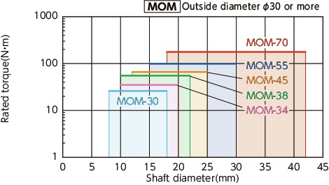
Selection example
In case of selected parameters of shaft diameter of φ6 and load torque of 4N•m, the selected size is MOM-17.
Comparison of rated torque


Spacer’s projection structure
Spacer’s projection structure allows large angular to be effortlessly accepted. It reduces burden on the shaft.

In the oldham-type coupling whose spacer has no projection, the spacer and hubs interfere with each other near outside diameter, so that the max. angular misalignment is small (1° – 1.5°) and that the bending moment arises on the shaft.
NBK’s oldham type coupling allows the angular misalignment to be easily accepted since the projection serves as support. Bending moment does not arise. Therefore, the max. angular misalignment is large (2°) and the burden on the shaft is reduced. MOM is provided with a projection by inserting a resin pin into the spacer.


