

XRP

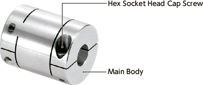
Rigid coupling – High precision – Clamping type
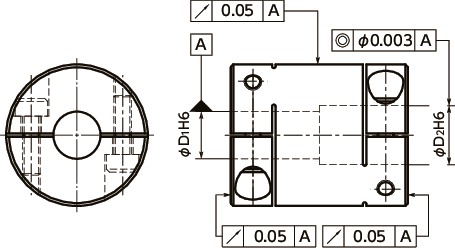
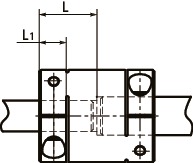
Dimension Drawing
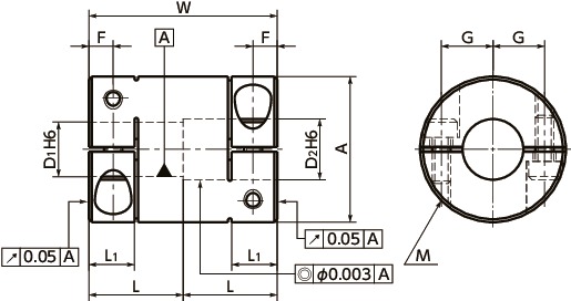
Dimensions/Specifications/CAD
| Part Number | A | L | L1 | W | F | G | M | Wrench Torque (N・m) |
|---|---|---|---|---|---|---|---|---|
| XRP-16C | 16 | 10 | 5 | 20 | 2.6 | 5 | M2 | 0.5 |
| XRP-19C | 19 | 13 | 6.5 | 26 | 3.5 | 6.25 | M2.5 | 1 |
| XRP-24C | 24 | 15 | 7 | 30 | 3.75 | 7.75 | M3 | 1.5 |
| XRP-34C | 34 | 20 | 8 | 40 | 4 | 12 | M3 | 1.5 |
| XRP-39C | 39 | 24 | 10 | 48 | 5 | 14.5 | M4 | 2.5 |
| Part Number | Max. Bore Diameter (mm) | Rated Torque* (N・m) | Max. Torque* (N・m) | Max. Rotational (min-1) | Mass** (g) |
|---|---|---|---|---|---|
| XRP-16C | 6 | 1 | 2 | 39000 | 9 |
| XRP-19C | 8 | 2.5 | 5 | 33000 | 15 |
| XRP-24C | 10 | 4.5 | 9 | 26000 | 32 |
| XRP-34C | 15 | 7.5 | 15 | 18000 | 87 |
| XRP-39C | 18 | 10 | 20 | 16000 | 140 |
* Correction of rated torque and max. torque due to load fluctuation is not required.
** These are values with max. bore diameter.
| Part Number | Stock Bores D1-D2 | ||
|---|---|---|---|
| XRP-16C | 5-5 | 5-6 | 6-6 |
| XRP-19C | 6-6 | 6-8 | 8-8 |
| XRP-24C | 8-8 | 8-10 | 10-10 |
| XRP-34C | 10-10 | 10-12 | 12-12 |
| XRP-39C | 12-12 | 12-14 | 15-15 |
All products are provided with hex socket set screws.
In a case where the bore diameter is φ 4 or less, the set screw is used in only one place.
Recommended dimensional allowances of applicable shaft diameter are h6 and h7.
Material/Finish
| XRP-C | |
|---|---|
| Main Body | A7075 |
| Hex Socket Head Cap Screw | SCM435 Ferrosoferric Oxide Film |
Structure
Clamping type
Characteristics
- Applicable motors
XRP-C Servomotor ◎ Stepping motor ◎ General-purpose motor – ◎:Excellent ○:Very good
- Property
XRP-C Zero Backlash ◎ High Torque ○ High Torsional Stiffness ◎ ◎:Excellent ○:Very good
- This is a high precision rigid coupling.
- Coaxiality, bore diameter, and run out have been pursued to the ultimate level.
- An inspection report is attached to all products before shipment.
- Light weight and ultra small moment of inertia. High response.
- This is a shaft fastening structure with consideration of rotational balance and unbalance is ultra small.
- Extra super duralumin (A7075) featuring the highest strength among aluminum alloy is adopted.
Application
High precision measurement device/High precision XY stage/Encoder
Selection
The area bounded by the shaft diameter and rated torque indicates is the selection size.
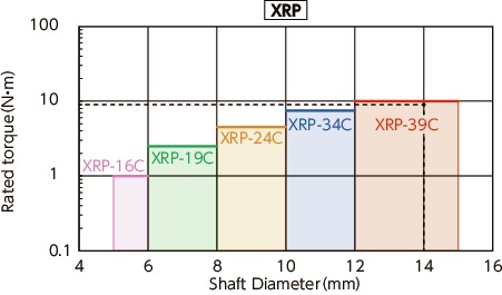
Selection example
In case of selected parameters of shaft diameter of φ14 and load torque of 9 N・m, the selection size is XRP-39C.
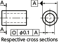
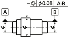
Commitment to high precision
- The coaxiality of both bores is not more than 3 μm.
- Bore diameter tolerance is H6.
- Radial run out and run out of end face against bore are not more than 50μm.

Precision assurance by total inspection
- The inspection is conducted in an environment of constant temperature and humidity.
- Inspection item:
Bore diameters D1 and D2
Coaxiality of bores D1 and D2
Radial run out and run out of end face against bore - 3D measurement device:
UPMC850CARAT SuperAcc made by Carl Zeiss

Shaft insertion length
The shaft insertion length should be not less than L1 (clamp portion) and not more than L.
The insertion length of a shaft to maintain the high precision should be L dimension if possible.
However, be careful so that both shaft ends do not interfere with each other.
If the shaft insertion length is less than L1, it may derange the coaxiality or generate vibration when fastening the shaft.
Concentricity tolerance and coaxiality tolerance


Comparison of rated torque
Values of rated torque and max. torque for XRP have been changed. Usage under the condition of higher torque than before is allowed.
| Part Number | Before Change | After Change | ||
|---|---|---|---|---|
| Rated torque (N・m) | Max. torque (N・m) | Rated torque (N・m) | Max. torque (N・m) | |
| XRP-16C | 0.6 | 1.2 | 1 | 2 |
| XRP-19C | 1.4 | 2.8 | 2.5 | 5 |
| XRP-24C | 2.3 | 4.6 | 4.5 | 9 |
| XRP-34C | 2.8 | 5.6 | 7.5 | 15 |
| XRP-39C | 4.7 | 9.4 | 10 | 20 |


