

Miki Pulley SFC Models

SFC-SA2 Types
Specifications
| Model | Type | Rated torque [N・m] |
Misalignment | Max. rotation speed [min-1] |
Torsional stiffness [N・m/rad] |
Axial stiffness [N/mm] |
Moment of inertia [kg・m2] |
Mass[kg] | ||
|---|---|---|---|---|---|---|---|---|---|---|
| Parallel[mm] | Angular[゜] | Axial[mm] | ||||||||
| SFC-002SA2 | C | 0.25 | 0.01 | 0.5 | ±0.04 | 10000 | 190 | 34 | 0.06×10⁻⁶ | 0.003 |
| SFC-005SA2 | C | 0.6 | 0.02 | 0.5 | ±0.05 | 10000 | 500 | 140 | 0.26×10⁻⁶ | 0.007 |
| SFC-010SA2 | C | 1 | 0.02 | 1 | ±0.1 | 10000 | 1400 | 140 | 0.58×10⁻⁶ | 0.011 |
| SFC-020SA2 | C | 2 | 0.02 | 1 | ±0.15 | 10000 | 3700 | 64 | 2.39×10⁻⁶ | 0.025 |
| SFC-025SA2 | C | 4 | 0.02 | 1 | ±0.19 | 10000 | 5600 | 60 | 3.67×10⁻⁶ | 0.029 |
| SFC-030SA2 | A | 5 | 0.02 | 1 | ±0.2 | 10000 | 8000 | 64 | 4.07×10⁻⁶ | 0.034 |
| B | 6.09×10⁻⁶ | 0.041 | ||||||||
| C | 8.20×10⁻⁶ | 0.049 | ||||||||
| SFC-035SA2 | C | 10 | 0.02 | 1 | ±0.25 | 10000 | 18000 | 112 | 18.44×10⁻⁶ | 0.082 |
| SFC-040SA2 | A | 12 | 0.02 | 1 | ±0.3 | 10000 | 20000 | 80 | 16.71×10⁻⁶ | 0.077 |
| B | 22.55×10⁻⁶ | 0.085 | ||||||||
| C | 29.25×10⁻⁶ | 0.100 | ||||||||
| SFC-050SA2 | A | 25 | 0.02 | 1 | ±0.4 | 10000 | 32000 | 48 | 55.71×10⁻⁶ | 0.159 |
| B | 76.26×10⁻⁶ | 0.177 | ||||||||
| C | 99.03×10⁻⁶ | 0.206 | ||||||||
| SFC-055SA2 | C | 40 | 0.02 | 1 | ±0.42 | 10000 | 50000 | 43 | 188.0×10⁻⁶ | 0.314 |
| SFC-060SA2 | A | 60 | 0.02 | 1 | ±0.45 | 10000 | 70000 | 76.4 | 145.9×10⁻⁶ | 0.283 |
| B | 205.0×10⁻⁶ | 0.326 | ||||||||
| C | 268.6×10⁻⁶ | 0.385 | ||||||||
| SFC-080SA2 | C | 100 | 0.02 | 1 | ±0.55 | 10000 | 140000 | 128 | 710.6×10⁻⁶ | 0.708 |
| SFC-090SA2 | C | 180 | 0.02 | 1 | ±0.65 | 10000 | 100000 | 108 | 1236×10-6 | 0.946 |
| SFC-100SA2 | C | 250 | 0.02 | 1 | ±0.74 | 10000 | 120000 | 111 | 1891×10-6 | 1.202 |
* Check the Standard Bore Diameter list as rated torque may be restricted by the holding power of the shaft connection component.
* Max. rotation speed does not take into account dynamic balance.
* Torsional stiffness values given are measured values for the element alone.
* The moment of inertia and mass are measured for the maximum bore diameter.
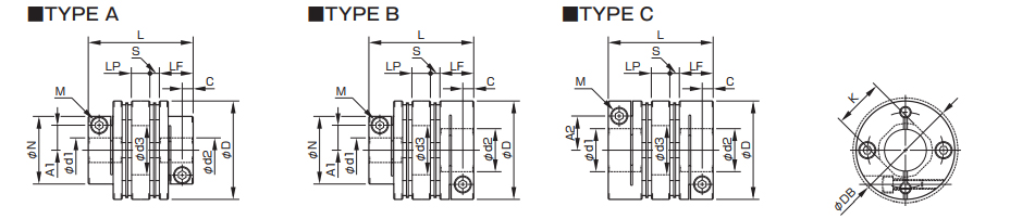
Dimensions

| Model | Type | d1[mm] | d2[mm] | D[mm] | DB[mm] | N[mm] | L[mm] | LF[mm] | S[mm] | A1[mm] | A2[mm] | C[mm] | K[mm] | M Qty – Nominal dia |
Tightening torque[N・m] | ||
|---|---|---|---|---|---|---|---|---|---|---|---|---|---|---|---|---|---|
| Min. | Max. | Min. | Max. | ||||||||||||||
| SFC-002SA2 | C | 3 | 5 | 3 | 5 | 12 | 12.4 | ─ | 12.35 | 5.9 | 0.55 | ─ | 3.7 | 1.9 | 5.6 | 1-M1.6 | 0.23~0.28 |
| SFC-005SA2 | C | 3 | 6 | 3 | 6 | 16 | ─ | ─ | 16.7 | 7.85 | 1 | ─ | 4.8 | 2.5 | 6.5 | 1-M2 | 0.4~0.5 |
| SFC-010SA2 | C | 3 | 8 | 3 | 8 | 19 | ─ | ─ | 19.35 | 9.15 | 1.05 | ─ | 5.8(6) | 3.15 | 8.5 | 1-M2.5(M2) | 1.0~1.1(0.4~0.5) |
| SFC-020SA2 | C | 4 | 10 | 4 | 11 | 26 | ─ | ─ | 23.15 | 10.75 | 1.65 | ─ | 9.5 | 3.3 | 10.6 | 1-M2.5 | 1.0~1.1 |
| SFC-025SA2 | C | 5 | 14 | 5 | 14 | 29 | ─ | ─ | 23.4 | 10.75 | 1.9 | ─ | 11 | 3.3 | 14.5 | 1-M2.5 | 1.0~1.1 |
| SFC-030SA2 | A | 5 | 10 | 5 | 10 | 34 | ─ | 21.6 | 27.3 | 12.4 | 2.5 | 8 | ─ | 3.75 | 14.5 | 1-M3 | 1.5~1.9 |
| B | 5 | 10 | Over 10 | 16 | 8 | 12.5 | |||||||||||
| C | Over 10 | 14 | Over 10 | 16 | ─ | ─ | 12.5 | ||||||||||
| SFC-035SA2 | C | 6 | 16 | 6 | 19 | 39 | ─ | ─ | 34 | 15.5 | 3 | ─ | 14 | 4.5 | 17 | 1-M4 | 3.4~4.1 |
| SFC-040SA2 | A | 8 | 15 | 8 | 15 | 44 | ─ | 29.6 | 34 | 15.5 | 3 | 11 | ─ | 4.5 | 19.5 | 1-M4 | 3.4~4.1 |
| B | 8 | 15 | Over 15 | 24 | 11 | 17 | |||||||||||
| C | Over 15 | 19 | Over 15 | 24 | ─ | ─ | 17 | ||||||||||
| SFC-050SA2 | A | 8 | 19 | 8 | 19 | 56 | ─ | 38 | 43.4 | 20.5 | 2.4 | 14.5 | ─ | 6 | 26 | 1-M5 | 7.0~8.5 |
| B | 8 | 19 | Over 19 | 30 | 14.5 | 22 | |||||||||||
| C | Over 19 | 25 | Over 19 | 30 | ─ | ─ | 22 | ||||||||||
| SFC-055SA2 | C | 10 | 30 | 10 | 30 | 63 | ─ | ─ | 50.6 | 24 | 2.6 | ─ | 23 | 7.75 | 31 | 1-M6 | 14~15 |
| SFC-060SA2 | A | 11 | 24 | 11 | 24 | 68 | ─ | 46 | 53.6 | 25.2 | 3.2 | 17.5 | ─ | 7.75 | 31 | 1-M6 | 14~15 |
| B | 11 | 24 | Over 24 | 35 | 17.5 | 26.5 | |||||||||||
| C | Over 24 | 30 | Over 24 | 35 | ─ | ─ | 26.5 | ||||||||||
| SFC-080SA2 | C | 18 | 35 | 18 | 40 | 82 | ─ | ─ | 68 | 30 | 8 | ─ | 28 | 9 | 38 | 1-M8 | 27~30 |
| SFC-090SA2 | C | 25 | 40 | 25 | 45 | 94 | ─ | ─ | 68.3 | 30 | 8.3 | ─ | 34 | 9 | 42 | 1-M8 | 27~30 |
| SFC-100SA2 | C | 32 | 45 | 32 | 45 | 104 | ─ | ─ | 69.8 | 30 | 9.8 | ─ | 39 | 9 | 48 | 1-M8 | 27~30 |
* The øDB value is measured assuming that the head of the clamping bolt is larger than the external diameter of the hub.
* The K dimension is the inner diameter of the element. For d2 dimension exceeding this value, shaft can be inserted only up to LF dimension to the d2 side hub.
* The nominal diameter for the clamping bolt M is equal to the quantity minus the nominal diameter of the screw threads, where the quantity is for a hub on one side.
* The figures in parentheses ( ) for the SFC-010 are the values when d1 or d2 is ø8 mm.
Standard bore diameter
| Standard (option) bore diameter, d1/d2 [mm] and restricted rated torque [N∙m] | |||||||||||||||||||||||||||||||||
|---|---|---|---|---|---|---|---|---|---|---|---|---|---|---|---|---|---|---|---|---|---|---|---|---|---|---|---|---|---|---|---|---|---|
| Nominal bore diameter | 3 | 4 | 5 | 6 | 6.35 | 7 | 8 | 9 | 9.525 | 10 | 11 | 12 | 13 | 14 | 15 | 16 | 17 | 18 | 19 | 20 | 22 | 24 | 25 | 28 | 30 | 32 | 35 | 38 | 40 | 42 | 45 | ||
| Shaft tolerance | h7(h6・g6) | B | ● | ● | ● | ● | ● | ● | ● | ● | ● | ● | ● | ● | ● | ● | ● | ● | ● | ● | ● | ● | ● | ● | ● | ● | ● | ● | ● | ● | ● | ● | ● |
| j6(Option) | J | ○ | ○ | ○ | ○ | ||||||||||||||||||||||||||||
| k6(Option) | K | ○ | ○ | ○ | ○ | ○ | ○ | ○ | ○ | ○ | |||||||||||||||||||||||
| Supported bore diameter for each mode |
SFC-002SA2 | d1 | ● | ● | ● | ||||||||||||||||||||||||||||
| d2 | ● | ● | ● | ||||||||||||||||||||||||||||||
| SFC-005SA2 | d1 | ● | ● | ● | ● | ||||||||||||||||||||||||||||
| d2 | ● | ● | ● | ● | |||||||||||||||||||||||||||||
| SFC-010SA2 | d1 | ● | ● | ● | ● | ● | ● | ● | |||||||||||||||||||||||||
| d2 | ● | ● | ● | ● | ● | ● | ● | ||||||||||||||||||||||||||
| SFC-020SA2 | d1 | ● | ● | ● | ● | ● | ● | ● | ● | ● | |||||||||||||||||||||||
| d2 | ● | ● | ● | ● | ● | ● | ● | ● | ● | ● | |||||||||||||||||||||||
| SFC-025SA2 | d1 | 2.1 | ● | ● | ● | ● | ● | ● | ● | ● | ● | ● | ● | ||||||||||||||||||||
| d2 | 2.1 | ● | ● | ● | ● | ● | ● | ● | ● | ● | ● | ● | |||||||||||||||||||||
| SFC-030SA2 | d1 | 2.8 | 3.4 | ● | ● | ● | ● | ● | ● | ● | ● | ● | ● | ||||||||||||||||||||
| d2 | 2.8 | 3.4 | ● | ● | ● | ● | ● | ● | ● | ● | ● | ● | ● | ● | |||||||||||||||||||
| SFC-035SA2 | d1 | 5 | 5 | 6.6 | ● | ● | ● | ● | ● | ● | ● | ● | ● | ● | |||||||||||||||||||
| d2 | 5 | 5 | 6.6 | ● | ● | ● | ● | ● | ● | ● | ● | ● | ● | ● | ● | ● | |||||||||||||||||
| SFC-040SA2 | d1 | 9 | ● | ● | ● | ● | ● | ● | ● | ● | ● | ● | ● | ● | |||||||||||||||||||
| d2 | 9 | ● | ● | ● | ● | ● | ● | ● | ● | ● | ● | ● | ● | ● | ● | ● | |||||||||||||||||
| SFC-050SA2 | d1 | 18 | 20 | 22 | 22 | ● | ● | ● | ● | ● | ● | ● | ● | ● | ● | ● | ● | ● | |||||||||||||||
| d2 | 18 | 20 | 22 | 22 | ● | ● | ● | ● | ● | ● | ● | ● | ● | ● | ● | ● | ● | ● | ● | ||||||||||||||
| SFC-055SA2 | d1 | 31 | 34 | 36 | 38 | ● | ● | ● | ● | ● | ● | ● | ● | ● | ● | ● | ● | ||||||||||||||||
| d2 | 31 | 34 | 36 | 38 | ● | ● | ● | ● | ● | ● | ● | ● | ● | ● | ● | ● | |||||||||||||||||
| SFC-060SA2 | d1 | 50 | 51 | ● | ● | ● | ● | ● | ● | ● | ● | ● | ● | ● | ● | ● | |||||||||||||||||
| d2 | 50 | 51 | ● | ● | ● | ● | ● | ● | ● | ● | ● | ● | ● | ● | ● | ● | ● | ||||||||||||||||
| SFC-080SA2 | d1 | ● | ● | ● | ● | ● | ● | ● | ● | ● | ● | ||||||||||||||||||||||
| d2 | ● | ● | ● | ● | ● | ● | ● | ● | ● | ● | ● | ● | |||||||||||||||||||||
| SFC-090SA2 | d1 | ● | ● | ● | ● | ● | ● | ● | |||||||||||||||||||||||||
| d2 | ● | ● | ● | ● | ● | ● | ● | ● | ● | ||||||||||||||||||||||||
| SFC-100SA2 | d1 | 226 | ● | ● | ● | ● | ● | ||||||||||||||||||||||||||
| d2 | 226 | ● | ● | ● | ● | ● | |||||||||||||||||||||||||||
* The shaft tolerance for standard bore diameter is h7 (h6 or g6): designation B. However, for a shaft diameter of ø35, the tolerance is + 0.010~- 0.025 .
* Shaft tolerances j6/k6: designations J/K are optional, and are only supported for bore diameters marked with ○ .
* Bore diameters marked with ● or numbers are supported as the standard bore diameters. Consult Miki Pulley regarding special arrangements which may be possible for other bore diameters.
* Bore diameters whose fields contain numbers are restricted in their rated torque by the holding power of the shaft connection component because the bore diameter is small. The numbers indicate the rated torque [N•m].

SFC-DA2 Types
Specifications
| Model | Type | Rated torque [N・m] |
Misalignment | Max. rotation speed [min-1] |
Torsional stiffness [N・m/rad] |
Axial stiffness [N/mm] |
Moment of inertia [kg・m2] |
Mass[kg] | ||
|---|---|---|---|---|---|---|---|---|---|---|
| Parallel[mm] | Angular[゜] | Axial[mm] | ||||||||
| SFC-002DA2 | C | 0.25 | 0.03 | 0.5(On one side) | ±0.08 | 10000 | 95 | 17 | 0.07×10⁻⁶ | 0.004 |
| SFC-005DA2 | C | 0.6 | 0.05 | 0.5(On one side) | ±0.1 | 10000 | 250 | 70 | 0.37×10⁻⁶ | 0.010 |
| SFC-010DA2 | C | 1 | 0.11 | 1(On one side) | ±0.2 | 10000 | 700 | 70 | 0.80×10⁻⁶ | 0.015 |
| SFC-020DA2 | C | 2 | 0.15 | 1(On one side) | ±0.33 | 10000 | 1850 | 32 | 3.43×10⁻⁶ | 0.035 |
| SFC-025DA2 | C | 4 | 0.16 | 1(On one side) | ±0.38 | 10000 | 2800 | 30 | 5.26×10⁻⁶ | 0.040 |
| SFC-030DA2 | A | 5 | 0.18 | 1(On one side) | ±0.4 | 10000 | 4000 | 32 | 7.43×10⁻⁶ | 0.054 |
| B | 9.45×10⁻⁶ | 0.060 | ||||||||
| C | 11.56×10⁻⁶ | 0.068 | ||||||||
| SFC-035DA2 | C | 10 | 0.24 | 1(On one side) | ±0.5 | 10000 | 9000 | 56 | 26.93×10⁻⁶ | 0.121 |
| SFC-040DA2 | A | 12 | 0.24 | 1(On one side) | ±0.6 | 10000 | 10000 | 40 | 29.98×10⁻⁶ | 0.124 |
| B | 35.82×10⁻⁶ | 0.131 | ||||||||
| C | 42.52×10⁻⁶ | 0.146 | ||||||||
| SFC-050DA2 | A | 25 | 0.28 | 1(On one side) | ±0.8 | 10000 | 16000 | 24 | 98.34×10⁻⁶ | 0.250 |
| B | 118.9×10⁻⁶ | 0.268 | ||||||||
| C | 141.7×10⁻⁶ | 0.298 | ||||||||
| SFC-055DA2 | C | 40 | 0.31 | 1(On one side) | ±0.84 | 10000 | 25000 | 21.5 | 261.3×10⁻⁶ | 0.459 |
| SFC-060DA2 | A | 60 | 0.34 | 1(On one side) | ±0.9 | 10000 | 35000 | 38.2 | 256.6×10⁻⁶ | 0.447 |
| B | 315.7×10⁻⁶ | 0.489 | ||||||||
| C | 379.3×10⁻⁶ | 0.549 | ||||||||
| SFC-080DA2 | C | 100 | 0.52 | 1(On one side) | ±1.10 | 10000 | 70000 | 64 | 1039×10-6 | 1.037 |
| SFC-090DA2 | C | 180 | 0.52 | 1(On one side) | ±1.30 | 10000 | 50000 | 54 | 1798×10-6 | 1.369 |
| SFC-100DA2 | C | 250 | 0.55 | 1(On one side) | ±1.48 | 10000 | 60000 | 55.5 | 2754×10-6 | 1.739 |
* Check the “Standard Bore Diameters” as rated torque may be restricted by the holding power of the shaft connection component.
* Max. rotation speed does not take into account dynamic balance.
* Torsional stiffness values given are measured values for the element alone
* The moment of inertia and mass are measured for the maximum bore diameter.
Dimensions
| Model | Type | d1[mm] | d2[mm] | D[mm] | DB[mm] | N[mm] | L[mm] | LF[mm] | LP[mm] | S[mm] | A1[mm] | A2[mm] | C[mm] | d3[mm] | K[mm] | M Qty – Nominal dia |
Tightening torque[N・m] | ||
|---|---|---|---|---|---|---|---|---|---|---|---|---|---|---|---|---|---|---|---|
| Min. | Max. | Min. | Max. | ||||||||||||||||
| SFC-002DA2 | C | 3 | 5 | 3 | 5 | 12 | 12.4 | ─ | 15.7 | 5.9 | 2.8 | 0.55 | ─ | 3.7 | 1.9 | 5.2 | 5.6 | 1-M1.6 | 0.23~0.28 |
| SFC-005DA2 | C | 3 | 6 | 3 | 6 | 16 | ─ | ─ | 23.2 | 7.85 | 5.5 | 1 | ─ | 4.8 | 2.5 | 6.5 | 6.5 | 1-M2 | 0.4~0.5 |
| SFC-010DA2 | C | 3 | 8 | 3 | 8 | 19 | ─ | ─ | 25.9 | 9.15 | 5.5 | 1.05 | ─ | 5.8(6) | 3.15 | 8.5 | 8.5 | 1-M2.5(M2) | 1.0~1.1(0.4~0.5) |
| SFC-020DA2 | C | 4 | 10 | 4 | 11 | 26 | ─ | ─ | 32.3 | 10.75 | 7.5 | 1.65 | ─ | 9.5 | 3.3 | 10.6 | 10.6 | 1-M2.5 | 1.0~1.1 |
| SFC-025DA2 | C | 5 | 14 | 5 | 14 | 29 | ─ | ─ | 32.8 | 10.75 | 7.5 | 1.9 | ─ | 11 | 3.3 | 15 | 14.5 | 1-M2.5 | 1.0~1.1 |
| SFC-030DA2 | A | 5 | 10 | 5 | 10 | 34 | ─ | 21.6 | 37.8 | 12.4 | 8 | 2.5 | 8 | ─ | 3.75 | 15 | 14.5 | 1-M3 | 1.5~1.9 |
| B | 5 | 10 | Over 10 | 16 | 8 | 12.5 | |||||||||||||
| C | Over 10 | 14 | Over 10 | 16 | ─ | ─ | 12.5 | ||||||||||||
| SFC-035DA2 | C | 6 | 16 | 6 | 19 | 39 | ─ | ─ | 48 | 15.5 | 11 | 3 | ─ | 14 | 4.5 | 17 | 17 | 1-M4 | 3.4~4.1 |
| SFC-040DA2 | A | 8 | 15 | 8 | 15 | 44 | ─ | 29.6 | 48 | 15.5 | 11 | 3 | 11 | ─ | 4.5 | 20 | 19.5 | 1-M4 | 3.4~4.1 |
| B | 8 | 15 | Over 15 | 24 | 11 | 17 | |||||||||||||
| C | Over 15 | 19 | Over 15 | 24 | ─ | ─ | 17 | ||||||||||||
| SFC-050DA2 | A | 8 | 19 | 8 | 19 | 56 | ─ | 38 | 59.8 | 20.5 | 14 | 2.4 | 14.5 | ─ | 6 | 26 | 26 | 1-M5 | 7.0~8.5 |
| B | 8 | 19 | Over 19 | 30 | 14.5 | 22 | |||||||||||||
| C | Over 19 | 25 | Over 19 | 30 | ─ | ─ | 22 | ||||||||||||
| SFC-055DA2 | C | 10 | 30 | 10 | 30 | 63 | ─ | ─ | 68.7 | 24 | 15.5 | 2.6 | ─ | 23 | 7.75 | 31 | 31 | 1-M6 | 14~15 |
| SFC-060DA2 | A | 11 | 24 | 11 | 24 | 68 | ─ | 46 | 73.3 | 25.2 | 16.5 | 3.2 | 17.5 | ─ | 7.75 | 31 | 31 | 1-M6 | 14~15 |
| B | 11 | 24 | Over 24 | 35 | 17.5 | 26.5 | |||||||||||||
| C | Over 24 | 30 | Over 24 | 35 | ─ | ─ | 26.5 | ||||||||||||
| SFC-080DA2 | C | 18 | 35 | 18 | 40 | 82 | ─ | ─ | 98 | 30 | 22 | 8 | ─ | 28 | 9 | 40 | 38 | 1-M8 | 27~30 |
| SFC-090DA2 | C | 25 | 40 | 25 | 45 | 94 | ─ | ─ | 98.6 | 30 | 22 | 8.3 | ─ | 34 | 9 | 47 | 42 | 1-M8 | 27~30 |
| SFC-100DA2 | C | 32 | 45 | 32 | 45 | 104 | ─ | ─ | 101.6 | 30 | 22 | 9.8 | ─ | 39 | 9 | 50 | 48 | 1-M8 | 27~30 |
* The øDB value is measured assuming that the head of the clamping bolt is larger than the external diameter of the hub.
* The K dimension is the inner diameter of the element. For d2 dimension exceeding this value, shaft can be inserted only up to LF dimension to the d2 side hub.
* The nominal diameter for the clamping bolt M is equal to the quantity minus the nominal diameter of the screw threads, where the quantity is for a hub on one side.
* The figures in parentheses ( ) for the SFC-010 are the values when d1 or d2 is ø8 mm.
Standard bore diameter
| Standard (option) bore diameter, d1/d2 [mm] and restricted rated torque [N∙m] | |||||||||||||||||||||||||||||||||
|---|---|---|---|---|---|---|---|---|---|---|---|---|---|---|---|---|---|---|---|---|---|---|---|---|---|---|---|---|---|---|---|---|---|
| Nominal bore diameter | 3 | 4 | 5 | 6 | 6.35 | 7 | 8 | 9 | 9.525 | 10 | 11 | 12 | 13 | 14 | 15 | 16 | 17 | 18 | 19 | 20 | 22 | 24 | 25 | 28 | 30 | 32 | 35 | 38 | 40 | 42 | 45 | ||
| Shaft tolerance | h7(h6・g6) | B | ● | ● | ● | ● | ● | ● | ● | ● | ● | ● | ● | ● | ● | ● | ● | ● | ● | ● | ● | ● | ● | ● | ● | ● | ● | ● | ● | ● | ● | ● | ● |
| j6(Option) | J | ○ | ○ | ○ | ○ | ||||||||||||||||||||||||||||
| k6(Option) | K | ○ | ○ | ○ | ○ | ○ | ○ | ○ | ○ | ○ | |||||||||||||||||||||||
| Supported bore diameter for each mode |
SFC-002DA2 | d1 | ● | ● | ● | ||||||||||||||||||||||||||||
| d2 | ● | ● | ● | ||||||||||||||||||||||||||||||
| SFC-005DA2 | d1 | ● | ● | ● | ● | ||||||||||||||||||||||||||||
| d2 | ● | ● | ● | ● | |||||||||||||||||||||||||||||
| SFC-010DA2 | d1 | ● | ● | ● | ● | ● | ● | ● | |||||||||||||||||||||||||
| d2 | ● | ● | ● | ● | ● | ● | ● | ||||||||||||||||||||||||||
| SFC-020DA2 | d1 | ● | ● | ● | ● | ● | ● | ● | ● | ● | |||||||||||||||||||||||
| d2 | ● | ● | ● | ● | ● | ● | ● | ● | ● | ● | |||||||||||||||||||||||
| SFC-025DA2 | d1 | 2.1 | ● | ● | ● | ● | ● | ● | ● | ● | ● | ● | ● | ||||||||||||||||||||
| d2 | 2.1 | ● | ● | ● | ● | ● | ● | ● | ● | ● | ● | ● | |||||||||||||||||||||
| SFC-030DA2 | d1 | 2.8 | 3.4 | ● | ● | ● | ● | ● | ● | ● | ● | ● | ● | ||||||||||||||||||||
| d2 | 2.8 | 3.4 | ● | ● | ● | ● | ● | ● | ● | ● | ● | ● | ● | ● | |||||||||||||||||||
| SFC-035DA2 | d1 | 5 | 5 | 6.6 | ● | ● | ● | ● | ● | ● | ● | ● | ● | ● | |||||||||||||||||||
| d2 | 5 | 5 | 6.6 | ● | ● | ● | ● | ● | ● | ● | ● | ● | ● | ● | ● | ● | |||||||||||||||||
| SFC-040DA2 | d1 | 9 | ● | ● | ● | ● | ● | ● | ● | ● | ● | ● | ● | ● | |||||||||||||||||||
| d2 | 9 | ● | ● | ● | ● | ● | ● | ● | ● | ● | ● | ● | ● | ● | ● | ● | |||||||||||||||||
| SFC-050DA2 | d1 | 18 | 20 | 22 | 22 | ● | ● | ● | ● | ● | ● | ● | ● | ● | ● | ● | ● | ● | |||||||||||||||
| d2 | 18 | 20 | 22 | 22 | ● | ● | ● | ● | ● | ● | ● | ● | ● | ● | ● | ● | ● | ● | ● | ||||||||||||||
| SFC-055DA2 | d1 | 31 | 34 | 36 | 38 | ● | ● | ● | ● | ● | ● | ● | ● | ● | ● | ● | ● | ||||||||||||||||
| d2 | 31 | 34 | 36 | 38 | ● | ● | ● | ● | ● | ● | ● | ● | ● | ● | ● | ● | |||||||||||||||||
| SFC-060DA2 | d1 | 50 | 51 | ● | ● | ● | ● | ● | ● | ● | ● | ● | ● | ● | ● | ● | |||||||||||||||||
| d2 | 50 | 51 | ● | ● | ● | ● | ● | ● | ● | ● | ● | ● | ● | ● | ● | ● | ● | ||||||||||||||||
| SFC-080DA2 | d1 | ● | ● | ● | ● | ● | ● | ● | ● | ● | ● | ||||||||||||||||||||||
| d2 | ● | ● | ● | ● | ● | ● | ● | ● | ● | ● | ● | ● | |||||||||||||||||||||
| SFC-090DA2 | d1 | ● | ● | ● | ● | ● | ● | ● | |||||||||||||||||||||||||
| d2 | ● | ● | ● | ● | ● | ● | ● | ● | ● | ||||||||||||||||||||||||
| SFC-100DA2 | d1 | 226 | ● | ● | ● | ● | ● | ||||||||||||||||||||||||||
| d2 | 226 | ● | ● | ● | ● | ● | |||||||||||||||||||||||||||
* The shaft tolerance for standard bore diameter is h7 (h6 or g6): designation B. However, for a shaft diameter of ø35, the tolerance is + 0.010~-0.025 .
* Shaft tolerances j6/k6: designations J/K are optional, and are only supported for bore diameters marked with ○ .
* Bore diameters marked with ● or numbers are supported as the standard bore diameters. Consult Miki Pulley regarding special arrangements which may be possible for other bore diameters.
* Bore diameters whose fields contain numbers are restricted in their rated torque by the holding power of the shaft connection component because the bore diameter is small. The numbers indicate the rated torque [N•m].


