

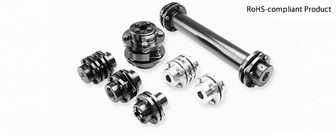
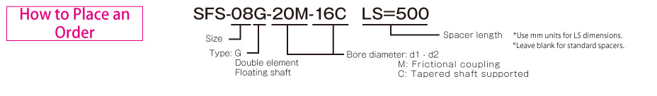
Miki Pulley SFS Models
SFS S Types
Specifications
| Model | Rated torque [N・m] | Misalignment | Max. rotation speed [min-1] | Torsional stiffness [N・m/rad] | Axial stiffness[N/mm] | Moment of inertia [kg・m2] | Mass [kg] | |
|---|---|---|---|---|---|---|---|---|
| Angular [°] | Axial [mm] | |||||||
| SFS-05S | 20 | 1 | ±0.6 | 25000 | 16000 | 43 | 0.11×10⁻³ | 0.30 |
| SFS-06S | 40 | 1 | ±0.8 | 20000 | 29000 | 45 | 0.30×10⁻³ | 0.50 |
| SFS-08S | 80 | 1 | ±1.0 | 17000 | 83000 | 60 | 0.87×10⁻³ | 1.00 |
| SFS-09S | 180 | 1 | ±1.2 | 15000 | 170000 | 122 | 1.60×10⁻³ | 1.40 |
| SFS-10S | 250 | 1 | ±1.4 | 13000 | 250000 | 160 | 2.60×10⁻³ | 2.10 |
| SFS-12S | 450 | 1 | ±1.6 | 11000 | 430000 | 197 | 6.50×10⁻³ | 3.40 |
| SFS-14S | 800 | 1 | ±1.8 | 9500 | 780000 | 313 | 9.90×10⁻³ | 4.90 |
| SFS-05S-C | 15 | 1 | ±0.6 | 25000 | 16000 | 43 | 0.11×10⁻³ | 0.30 |
| SFS-06S-C | 30 | 1 | ±0.8 | 20000 | 29000 | 45 | 0.30×10⁻³ | 0.50 |
| SFS-08S-C | 60 | 1 | ±1.0 | 17000 | 83000 | 60 | 0.87×10⁻³ | 1.00 |
| SFS-09S-C | 135 | 1 | ±1.2 | 15000 | 170000 | 122 | 1.60×10⁻³ | 1.40 |
| SFS-10S-C | 190 | 1 | ±1.4 | 13000 | 250000 | 160 | 2.60×10⁻³ | 2.10 |
| SFS-12S-C | 340 | 1 | ±1.6 | 11000 | 430000 | 197 | 6.50×10⁻³ | 3.40 |
| SFS-14S-C | 600 | 1 | ±1.8 | 9500 | 780000 | 313 | 9.90×10⁻³ | 4.90 |
| SFS-06S-□M-□M | 40 | 1 | ±0.8 | 5000 | 29000 | 45 | 0.30×10⁻³ | 0.70 |
| SFS-08S-□M-□M | 80 | 1 | ±1.0 | 5000 | 83000 | 60 | 0.93×10⁻³ | 1.30 |
| SFS-09S-□M-□M | 180 | 1 | ±1.2 | 5000 | 170000 | 122 | 1.80×10⁻³ | 1.80 |
| SFS-10S-□M-□M | 250 | 1 | ±1.4 | 5000 | 250000 | 160 | 2.70×10⁻³ | 2.30 |
| SFS-12S-□M-□M | 450 | 1 | ±1.6 | 5000 | 430000 | 197 | 6.80×10⁻³ | 4.10 |
| SFS-14S-35M-35M | 580 | 1 | ±1.8 | 5000 | 780000 | 313 | 14.01×10⁻³ | 6.40 |
| SFS-06S-□M-11C | 40 | 1 | ±0.8 | 5000 | 29000 | 45 | 0.29×10⁻³ | 0.60 |
| SFS-06S-15M-16C | 40 | 1 | ±0.8 | 5000 | 29000 | 45 | 0.34×10⁻³ | 0.70 |
| SFS-08S-□M-16C | 80 | 1 | ±1.0 | 5000 | 83000 | 60 | 0.84×10⁻³ | 1.20 |
| SFS-09S-□M-16C | 180 | 1 | ±1.2 | 5000 | 170000 | 122 | 1.50×10⁻³ | 1.60 |
*Max. rotation speed does not take into account dynamic balance.
*The moment of inertia and mass are measured for the maximum bore diameter.
Dimensions

| Model | d1, d2 | D | N | L | LF | S | F | K | M | ||
|---|---|---|---|---|---|---|---|---|---|---|---|
| Pilot bore | Min. | Max. | |||||||||
| SFS-05S | 7 | 8 | 20 | 56 | 32 | 45 | 20 | 5 | 11 | 24 | 4-M5×22 |
| SFS-06S | 7 | 8 | 25 | 68 | 40 | 56 | 25 | 6 | 10 | 30 | 4-M6×25 |
| SFS-08S | 10 | 11 | 35 | 82 | 54 | 66 | 30 | 6 | 11 | 38 | 4-M6×29 |
| SFS-09S | 10 | 11 | 38 | 94 | 58 | 68 | 30 | 8 | 21 | 42 | 4-M8×36 |
| SFS-10S | 15 | 16 | 42 | 104 | 68 | 80 | 35 | 10 | 16 | 48 | 4-M8×36 |
| SFS-12S | 18 | 19 | 50 | 126 | 78 | 91 | 40 | 11 | 23 | 54 | 4-M10×45 |
| SFS-14S | 20 | 22 | 60 | 144 | 88 | 102 | 45 | 12 | 31 | 61 | 4-M12×54 |
*Pilot bores are to be drilled into the part. See the standard hole-drilling standards for information on bore drilling.
*The nominal diameter of the reamer bolt is equal to the quantity minus the nominal diameter of the screw threads times the nominal length.

Dimensions
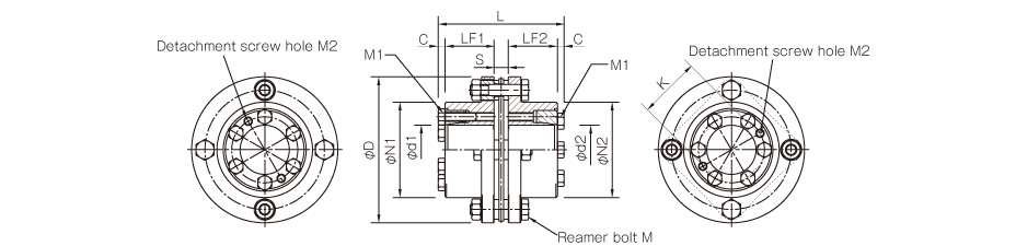
| Model | Bore diameter | d1 | d2 | D | N1 | N2 | L | LF1 | LF2 | S | C | K | M | M1 | M2 |
|---|---|---|---|---|---|---|---|---|---|---|---|---|---|---|---|
| SFS-06S | □M-□M | 12, 14, 15 | 12, 14, 15 | 68 | 40 | 40 | 65.6 | 25 | 25 | 6 | 4.8 | 30 | 4-M6×25 | 4-M5 | 2-M5 |
| SFS-08S | □M-□M | 15, 16, 20, 22 | 15, 16, 20, 22 | 82 | 54 | 54 | 75.6 | 30 | 30 | 6 | 4.8 | 38 | 4-M6×29 | 4-M6 | 2-M6 |
| SFS-09S | □M-□M | 25, 28 | 25, 28 | 94 | 58 | 58 | 77.6 | 30 | 30 | 8 | 4.8 | 42 | 4-M8×36 | 6-M6 | 2-M6 |
| □M-35M | 25, 28 | 35 | 68 | 85.6 | 38 | ||||||||||
| SFS-10S | □M-□M | 25, 28, 30, 35 | 25, 28, 30, 35 | 104 | 68 | 68 | 89.6 | 35 | 35 | 10 | 4.8 | 48 | 4-M8×36 | 6-M6 | 2-M6 |
| SFS-12S | □M-□M*1 | 30, 35 | 30, 35 | 126 | 78 | 78 | 101.6 | 40 | 40 | 11 | 5.3 | 54 | 4-M10×45 | 4-M8 | 2-M8 |
| SFS-14S | 35M-35M | 35 | 35 | 144 | 88 | 88 | 112.6 | 45 | 45 | 12 | 5.3 | 61 | 4-M12×54 | 6-M8 | 2-M8 |
*The nominal diameters of each bolt and tap are equal to the quantity minus the nominal diameter of the screw threads times the nominal length. The quantities for the pressure bolt M1 and detachment screw hole M2 are quantities for the hub on one side.
*The rated torque of SFS-12S-30M- □ M in note *1 is limited by the ø30 shaft coupling mechanism and is 380 N·m.
*The recommended processing tolerance for paired mounting shafts is h7(h6・g6) class. However, for a shaft diameter of ø35, the tolerance is -0.025 to +0.010.
*For non-standard hole diameters, the allowable torque may be subject to restrictions. Please check.

Dimensions
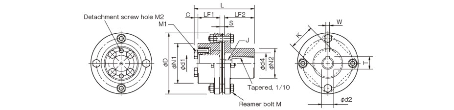
| Model | Bore diameter | d1 | d2 | W+0.030-0 | T+0.30-0 | d4 | J | D | N1 | N2 | L | LF1 | LF2 | S | C | K | M | M1 | M2 |
|---|---|---|---|---|---|---|---|---|---|---|---|---|---|---|---|---|---|---|---|
| SFS-06S | □M-11C | 12, 14, 15 | 11 | 4 | 12.2 | 18 | 9 | 68 | 40 | 30 | 60.8 | 25 | 25 | 6 | 4.8 | 30 | 4-M6×25 | 4-M5 | 2-M5 |
| 15M-16C | 15 | 16 | 5 | 17.3 | 28 | 10 | 40 | 75.8 | 40 | ||||||||||
| SFS-08S | □M-16C | 15, 16, 20, 22 | 16 | 5 | 17.3 | 28 | 10 | 82 | 54 | 40 | 80.8 | 30 | 40 | 6 | 4.8 | 38 | 4-M6×29 | 4-M6 | 2-M6 |
| SFS-09S | □M-16C | 25, 28 | 16 | 5 | 17.3 | 28 | 10 | 94 | 58 | 40 | 82.8 | 30 | 40 | 8 | 4.8 | 42 | 4-M8×36 | 6-M6 | 2-M6 |
*The nominal diameters of each bolt and tap are equal to the quantity minus the nominal diameter of the screw threads times the nominal length.
*The recommended processing tolerance for paired mounting shafts of the hub on the friction-coupled side is h7(h6・g6).
*For non-standard hole diameters, the allowable torque may be subject to restrictions. Please check.

SFS W Types
Specifications
| Model | Rated torque [N・m] | Misalignment | Max. rotation speed [min-1] | Torsional stiffness [N・m/rad] | Axial stiffness[N/mm] | Moment of inertia [kg・m2] | Mass [kg] | ||
|---|---|---|---|---|---|---|---|---|---|
| Parallel [mm] | Angular [°] | Axial [mm] | |||||||
| SFS-05W | 20 | 0.2 | 1 (On one side) | ±1.2 | 10000 | 8000 | 21 | 0.14×10⁻³ | 0.40 |
| SFS-06W | 40 | 0.3 | 1 (On one side) | ±1.6 | 8000 | 14000 | 22 | 0.41×10⁻³ | 0.70 |
| SFS-08W | 80 | 0.3 | 1 (On one side) | ±2.0 | 6800 | 41000 | 30 | 1.10×10⁻³ | 1.30 |
| SFS-09W | 180 | 0.5 | 1 (On one side) | ±2.4 | 6000 | 85000 | 61 | 2.20×10⁻³ | 2.10 |
| SFS-10W | 250 | 0.5 | 1 (On one side) | ±2.8 | 5200 | 125000 | 80 | 3.60×10⁻³ | 2.80 |
| SFS-12W | 450 | 0.6 | 1 (On one side) | ±3.2 | 4400 | 215000 | 98 | 9.20×10⁻³ | 4.90 |
| SFS-14W | 800 | 0.7 | 1 (On one side) | ±3.6 | 3800 | 390000 | 156 | 15.00×10⁻³ | 7.10 |
| SFS-05W-C | 15 | 0.2 | 1 (On one side) | ±1.2 | 10000 | 8000 | 21 | 0.14×10⁻³ | 0.40 |
| SFS-06W-C | 30 | 0.3 | 1 (On one side) | ±1.6 | 8000 | 14000 | 22 | 0.41×10⁻³ | 0.70 |
| SFS-08W-C | 60 | 0.3 | 1 (On one side) | ±2.0 | 6800 | 41000 | 30 | 1.10×10⁻³ | 1.30 |
| SFS-09W-C | 135 | 0.5 | 1 (On one side) | ±2.4 | 6000 | 85000 | 61 | 2.20×10⁻³ | 2.10 |
| SFS-10W-C | 190 | 0.5 | 1 (On one side) | ±2.8 | 5200 | 125000 | 80 | 3.60×10⁻³ | 2.80 |
| SFS-12W-C | 340 | 0.6 | 1 (On one side) | ±3.2 | 4400 | 215000 | 98 | 9.20×10⁻³ | 4.90 |
| SFS-14W-C | 600 | 0.7 | 1 (On one side) | ±3.6 | 3800 | 390000 | 156 | 15.00×10⁻³ | 7.10 |
| SFS-06W-□M-□M | 40 | 0.3 | 1 (On one side) | ±1.6 | 5000 | 14000 | 22 | 0.41×10⁻³ | 0.90 |
| SFS-08W-□M-□M | 80 | 0.3 | 1 (On one side) | ±2.0 | 5000 | 41000 | 30 | 1.16×10⁻³ | 1.60 |
| SFS-09W-□M-□M | 180 | 0.5 | 1 (On one side) | ±2.4 | 5000 | 85000 | 61 | 2.40×10⁻³ | 2.50 |
| SFS-10W-□M-□M | 250 | 0.5 | 1 (On one side) | ±2.8 | 5000 | 125000 | 80 | 3.70×10⁻³ | 3.00 |
| SFS-12W-□M-□M | 450 | 0.6 | 1 (On one side) | ±3.2 | 4400 | 215000 | 98 | 9.50×10⁻³ | 5.60 |
| SFS-14W-35M-35M | 580 | 0.7 | 1 (On one side) | ±3.6 | 3800 | 390000 | 156 | 19.11×10⁻³ | 8.60 |
| SFS-06W-□M-11C | 40 | 0.3 | 1 (On one side) | ±1.6 | 5000 | 14000 | 22 | 0.40×10⁻³ | 0.80 |
| SFS-06W-15M-16C | 40 | 0.3 | 1 (On one side) | ±1.6 | 5000 | 14000 | 22 | 0.45×10⁻³ | 0.90 |
| SFS-08W-□M-16C | 80 | 0.3 | 1 (On one side) | ±2.0 | 5000 | 41000 | 30 | 1.07×10⁻³ | 1.50 |
| SFS-09W-□M-16C | 180 | 0.5 | 1 (On one side) | ±2.4 | 5000 | 85000 | 61 | 2.10×10⁻³ | 2.30 |
*Max. rotation speed does not take into account dynamic balance.
*The moment of inertia and mass are measured for the maximum bore diameter.
Dimensions

| Model | d1, d2 | D | N | L | LF | LP | S | F | d3 | K | M | ||
|---|---|---|---|---|---|---|---|---|---|---|---|---|---|
| Pilot bore | Min. | Max. | |||||||||||
| SFS-05W | 7 | 8 | 20 | 56 | 32 | 58 | 20 | 8 | 5 | 4 | 20 | 24 | 8-M5×15 |
| SFS-06W | 7 | 8 | 25 | 68 | 40 | 74 | 25 | 12 | 6 | 3 | 24 | 30 | 8-M6×18 |
| SFS-08W | 10 | 11 | 35 | 82 | 54 | 84 | 30 | 12 | 6 | 2 | 28 | 38 | 8-M6×20 |
| SFS-09W | 10 | 11 | 38 | 94 | 58 | 98 | 30 | 22 | 8 | 12 | 32 | 42 | 8-M8×27 |
| SFS-10W | 15 | 16 | 42 | 104 | 68 | 110 | 35 | 20 | 10 | 7 | 34 | 48 | 8-M8×27 |
| SFS-12W | 18 | 19 | 50 | 126 | 78 | 127 | 40 | 25 | 11 | 10 | 40 | 54 | 8-M10×32 |
| SFS-14W | 20 | 22 | 60 | 144 | 88 | 144 | 45 | 30 | 12 | 15 | 46 | 61 | 8-M12×38 |
*Pilot bores are to be drilled into the part. See the standard hole-drilling standards for information on bore drilling.
*The nominal diameter of the reamer bolt is equal to the quantity minus the nominal diameter of the screw threads times the nominal length.

Dimensions

| Model | Bore diameter | d1 | d2 | D | N1 | N2 | L | LF1 | LF2 | LP | S | C | d3 | K | M | M1 | M2 |
|---|---|---|---|---|---|---|---|---|---|---|---|---|---|---|---|---|---|
| SFS-06W | □M-□M | 12, 14, 15 | 12, 14, 15 | 68 | 40 | 40 | 83.6 | 25 | 25 | 12 | 6 | 4.8 | 24 | 30 | 8-M6×18 | 4-M5 | 2-M5 |
| SFS-08W | □M-□M | 15, 16, 20, 22 | 15, 16, 20, 22 | 82 | 54 | 54 | 93.6 | 30 | 30 | 12 | 6 | 4.8 | 28 | 38 | 8-M6×20 | 4-M6 | 2-M6 |
| SFS-09W | □M-□M | 25, 28 | 25, 28 | 94 | 58 | 58 | 107.6 | 30 | 30 | 22 | 8 | 4.8 | 32 | 42 | 8-M8×27 | 6-M6 | 2-M6 |
| □M-35M | 25, 28 | 35 | 68 | 115.6 | 38 | ||||||||||||
| SFS-10W | □M-□M | 25, 28, 30, 35 | 25, 28, 30, 35 | 104 | 68 | 68 | 119.6 | 35 | 35 | 20 | 10 | 4.8 | 34 | 48 | 8-M8×27 | 6-M6 | 2-M6 |
| SFS-12W | □M-□M*1 | 30, 35 | 30, 35 | 126 | 78 | 78 | 137.6 | 40 | 40 | 25 | 11 | 5.3 | 40 | 54 | 8-M10×32 | 4-M8 | 2-M8 |
| SFS-14W | 35M-35M | 35 | 35 | 144 | 88 | 88 | 154.6 | 45 | 45 | 30 | 12 | 5.3 | 46 | 61 | 8-M12×38 | 6-M8 | 2-M8 |
*The nominal diameters of each bolt and tap are equal to the quantity minus the nominal diameter of the screw threads times the nominal length. The quantities for the pressure bolt M1 and detachment screw hole M2 are quantities for the hub on one side.
*The rated torque of SFS-12W-30M- □ M in note *1 is limited by the ø35 shaft coupling mechanism and is 380 N·m.
*The recommended processing tolerance for paired mounting shafts is h7(h6・g6) class. However, for a shaft diameter of ø35, the tolerance is -0.025 to +0.010.
*For non-standard hole diameters, the allowable torque may be subject to restrictions. Please check.

Dimensions

| Model | Bore diameter | d1 | d2 | W+0.030-0 | T+0.3-0 | d4 | J | D | N1 | N2 | L | LF1 | LF2 | LP | S | C | d3 | K | M | M1 | M2 |
|---|---|---|---|---|---|---|---|---|---|---|---|---|---|---|---|---|---|---|---|---|---|
| SFS-06W | □M-11C | 12, 14, 15 | 11 | 4 | 12.2 | 18 | 9 | 68 | 40 | 30 | 78.8 | 25 | 25 | 12 | 6 | 4.8 | 24 | 30 | 8-M6×18 | 4-M5 | 2-M5 |
| 15M-16C | 15 | 16 | 5 | 17.3 | 28 | 10 | 40 | 93.8 | 40 | ||||||||||||
| SFS-08W | □M-16C | 15, 16, 20, 22 | 16 | 5 | 17.3 | 28 | 10 | 82 | 54 | 40 | 98.8 | 30 | 40 | 12 | 6 | 4.8 | 28 | 38 | 8-M6×20 | 4-M6 | 2-M6 |
| SFS-09W | □M-16C | 25, 28 | 16 | 5 | 17.3 | 28 | 10 | 94 | 58 | 40 | 112.8 | 30 | 40 | 22 | 8 | 4.8 | 32 | 42 | 8-M8×27 | 6-M6 | 2-M6 |
*The nominal diameters of each bolt and tap are equal to the quantity minus the nominal diameter of the screw threads times the nominal length.
*The recommended processing tolerance for paired mounting shafts of the hub on the friction-coupled side is h7(h6・g6).
*For non-standard hole diameters, the allowable torque may be subject to restrictions. Please check.

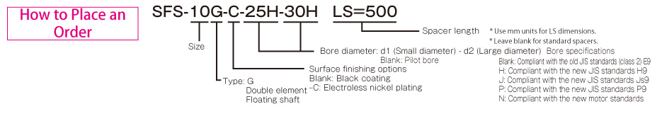
SFS G Types
Specifications
| Model | Rated torque [N・m] | Misalignment | Max. rotation speed [min-1] | Torsional stiffness [N・m/rad] | Axial stiffness[N/mm] | Moment of inertia [kg・m2] | Mass [kg] | ||
|---|---|---|---|---|---|---|---|---|---|
| Parallel [mm] | Angular [°] | Axial [mm] | |||||||
| SFS-05G | 20 | 0.5 | 1 (On one side) | ±1.2 | 20000 | 8000 | 21 | 0.20×10⁻³ | 0.50 |
| SFS-06G | 40 | 0.5 | 1 (On one side) | ±1.6 | 16000 | 14000 | 22 | 0.55×10⁻³ | 0.90 |
| SFS-08G | 80 | 0.5 | 1 (On one side) | ±2.0 | 13000 | 41000 | 30 | 1.50×10⁻³ | 1.70 |
| SFS-09G | 180 | 0.6 | 1 (On one side) | ±2.4 | 12000 | 85000 | 61 | 2.90×10⁻³ | 2.40 |
| SFS-10G | 250 | 0.6 | 1 (On one side) | ±2.8 | 10000 | 125000 | 80 | 4.60×10⁻³ | 3.30 |
| SFS-12G | 450 | 0.8 | 1 (On one side) | ±3.2 | 8000 | 215000 | 98 | 11.80×10⁻³ | 5.80 |
| SFS-14G | 800 | 0.9 | 1 (On one side) | ±3.6 | 7000 | 390000 | 156 | 21.20×10⁻³ | 8.60 |
| SFS-05G-C | 15 | 0.5 | 1 (On one side) | ±1.2 | 20000 | 8000 | 21 | 0.20×10⁻³ | 0.50 |
| SFS-06G-C | 30 | 0.5 | 1 (On one side) | ±1.6 | 16000 | 14000 | 22 | 0.55×10⁻³ | 0.90 |
| SFS-08G-C | 60 | 0.5 | 1 (On one side) | ±2.0 | 13000 | 41000 | 30 | 1.50×10⁻³ | 1.70 |
| SFS-09G-C | 135 | 0.6 | 1 (On one side) | ±2.4 | 12000 | 85000 | 61 | 2.90×10⁻³ | 2.40 |
| SFS-10G-C | 190 | 0.6 | 1 (On one side) | ±2.8 | 10000 | 125000 | 80 | 4.60×10⁻³ | 3.30 |
| SFS-12G-C | 340 | 0.8 | 1 (On one side) | ±3.2 | 8000 | 215000 | 98 | 11.80×10⁻³ | 5.80 |
| SFS-14G-C | 600 | 0.9 | 1 (On one side) | ±3.6 | 7000 | 390000 | 156 | 21.20×10⁻³ | 8.60 |
| SFS-06G-□M-□M | 40 | 0.5 | 1 (On one side) | ±1.6 | 5000 | 14000 | 22 | 0.55×10⁻³ | 1.10 |
| SFS-08G-□M-□M | 80 | 0.5 | 1 (On one side) | ±2.0 | 5000 | 41000 | 30 | 1.56×10⁻³ | 2.00 |
| SFS-09G-□M-□M | 180 | 0.6 | 1 (On one side) | ±2.4 | 5000 | 85000 | 61 | 3.10×10⁻³ | 2.80 |
| SFS-10G-□M-□M | 250 | 0.6 | 1 (On one side) | ±2.8 | 5000 | 125000 | 80 | 4.70×10⁻³ | 3.50 |
| SFS-12G-□M-□M | 450 | 0.8 | 1 (On one side) | ±3.2 | 5000 | 215000 | 98 | 12.10×10⁻³ | 6.50 |
| SFS-14G-35M-35M | 580 | 0.9 | 1 (On one side) | ±3.6 | 5000 | 390000 | 156 | 25.31×10⁻³ | 10.10 |
| SFS-06G-□M-11C | 40 | 0.5 | 1 (On one side) | ±1.6 | 5000 | 14000 | 22 | 0.54×10⁻³ | 1.00 |
| SFS-06G-15M-16C | 40 | 0.5 | 1 (On one side) | ±1.6 | 5000 | 14000 | 22 | 0.59×10⁻³ | 1.10 |
| SFS-08G-□M-16C | 80 | 0.5 | 1 (On one side) | ±2.0 | 5000 | 41000 | 30 | 1.47×10⁻³ | 1.90 |
| SFS-09G-□M-16C | 180 | 0.6 | 1 (On one side) | ±2.4 | 5000 | 85000 | 61 | 2.80×10⁻³ | 2.60 |
*Max. rotation speed does not take into account dynamic balance.
*The moment of inertia and mass are measured for the maximum bore diameter.
Dimensions

| Model | d1, d2 | D | N | L | LF | LS | S | F | K | M | ||
|---|---|---|---|---|---|---|---|---|---|---|---|---|
| Pilot bore | Min. | Max. | ||||||||||
| SFS-05G | 7 | 8 | 20 | 56 | 32 | 74 | 20 | 24 | 5 | 11 | 24 | 8-M5×22 |
| SFS-06G | 7 | 8 | 25 | 68 | 40 | 86 | 25 | 24 | 6 | 10 | 30 | 8-M6×25 |
| SFS-08G | 10 | 11 | 35 | 82 | 54 | 98 | 30 | 26 | 6 | 11 | 38 | 8-M6×29 |
| SFS-09G | 10 | 11 | 38 | 94 | 58 | 106 | 30 | 30 | 8 | 21 | 42 | 8-M8×36 |
| SFS-10G | 15 | 16 | 42 | 104 | 68 | 120 | 35 | 30 | 10 | 16 | 48 | 8-M8×36 |
| SFS-12G | 18 | 19 | 50 | 126 | 78 | 140 | 40 | 38 | 11 | 23 | 54 | 8-M10×45 |
| SFS-14G | 20 | 22 | 60 | 144 | 88 | 160 | 45 | 46 | 12 | 31 | 61 | 8-M12×54 |
*Pilot bores are to be drilled into the part. See the standard hole-drilling standards for information on bore drilling.
*If you require a product with an LS dimension other than that above, contact Miki Pulley with your required dimension. Please contact Miki Pulley for assistance if LS ≧ 1000.
*Please note that when the LS dimension exceeds 100 mm with the electroless nickel plating option (SFS- □ G-C), the insertion length of the shaft cannot exceed the LS dimension.
*The nominal diameter of the reamer bolt M is equal to the quantity minus the nominal diameter of the screw threads times the nominal length.
Dimensions

| Model | Bore diameter | d1 | d2 | D | N1 | N2 | L | LF1 | LF2 | LS | S | C | K | M | M1 | M2 |
|---|---|---|---|---|---|---|---|---|---|---|---|---|---|---|---|---|
| SFS-06G | □M-□M | 12, 14, 15 | 12, 14, 15 | 68 | 40 | 40 | 95.6 | 25 | 25 | 24 | 6 | 4.8 | 30 | 8-M6×25 | 4-M5 | 2-M5 |
| SFS-08G | □M-□M | 15, 16, 20, 22 | 15, 16, 20, 22 | 82 | 54 | 54 | 107.6 | 30 | 30 | 26 | 6 | 4.8 | 38 | 8-M6×29 | 4-M6 | 2-M6 |
| SFS-09G | □M-□M | 25, 28 | 25, 28 | 94 | 58 | 58 | 115.6 | 30 | 30 | 30 | 8 | 4.8 | 42 | 8-M8×36 | 6-M6 | 2-M6 |
| □M-35M | 25, 28 | 35 | 68 | 123.6 | 38 | |||||||||||
| SFS-10G | □M-□M | 25, 28, 30, 35 | 25, 28, 30, 35 | 104 | 68 | 68 | 129.6 | 35 | 35 | 30 | 10 | 4.8 | 48 | 8-M8×36 | 6-M6 | 2-M6 |
| SFS-12G | □M-□M*1 | 30, 35 | 30, 35 | 126 | 78 | 78 | 150.6 | 40 | 40 | 38 | 11 | 5.3 | 54 | 8-M10×45 | 4-M8 | 2-M8 |
| SFS-14G | 35M-35M | 35 | 35 | 144 | 88 | 88 | 170.6 | 45 | 45 | 46 | 12 | 5.3 | 61 | 8-M12×54 | 6-M8 | 2-M8 |
*If you require a product with an LS dimension other than that above, contact Miki Pulley with your required dimension. Please contact Miki Pulley for assistance if LS ≧ 1000.
*The nominal diameters of each bolt and tap are equal to the quantity minus the nominal diameter of the screw threads times the nominal length. The quantities for the pressure bolt M1 and detachment screw hole M2 are quantities for the hub on one side.
*The rated torque of SFS-12G-30M- □ M in note *1 is limited by the ø30 shaft coupling mechanism and is 380 N·m.
*The recommended processing tolerance for paired mounting shafts is h7(h6・g6) class. However, for a shaft diameter of ø35, the tolerance is -0.025 to +0.010.
*For non-standard hole diameters, the allowable torque may be subject to restrictions. Please check.

Dimensions

| Model | Bore diameter | d1 | d2 | W+0.030-0 | T+0.3-0 | d4 | J | D | N1 | N2 | L | LF1 | LF2 | LS | S | C | K | M | M1 | M2 |
|---|---|---|---|---|---|---|---|---|---|---|---|---|---|---|---|---|---|---|---|---|
| SFS-06G | □M-11C | 12, 14, 15 | 11 | 4 | 12.2 | 18 | 9 | 68 | 40 | 30 | 90.8 | 25 | 25 | 24 | 6 | 4.8 | 30 | 8-M6×25 | 4-M5 | 2-M5 |
| 15M-16C | 15 | 16 | 5 | 17.3 | 28 | 10 | 40 | 105.8 | 40 | |||||||||||
| SFS-08G | □M-16C | 15, 16, 20, 22 | 16 | 5 | 17.3 | 28 | 10 | 82 | 54 | 40 | 112.8 | 30 | 40 | 26 | 6 | 4.8 | 38 | 8-M6×29 | 4-M6 | 2-M6 |
| SFS-09G | □M-16C | 25, 28 | 16 | 5 | 17.3 | 28 | 10 | 94 | 58 | 40 | 120.8 | 30 | 40 | 30 | 8 | 4.8 | 42 | 8-M8×36 | 6-M6 | 2-M6 |
*If you require a product with an LS dimension other than that above, contact Miki Pulley with your required dimension. Please contact Miki Pulley for assistance if LS ≧ 1000.
*The nominal diameters of each bolt and tap are equal to the quantity minus the nominal diameter of the screw threads times the nominal length.
*The recommended processing tolerance for paired mounting shafts of the hub on the friction-coupled side is h7(h6・g6).
*For non-standard hole diameters, the allowable torque may be subject to restrictions. Please check.
Standard Hole-drilling Standards
| Models compliant with the old JIS standards (Class 2) |
Models compliant with the new JIS standards (H9) |
Models compliant with the new JIS standards (Js 9) |
Models compliant with the new JIS standards (P9) |
||||||||||||||||
|---|---|---|---|---|---|---|---|---|---|---|---|---|---|---|---|---|---|---|---|
| Nominal bore diameter | Bore diameter (d1, d2) | Keyway width (W1, W2) |
Keyway height (T1, T2) | Set screw hole (M) | Nominal bore diameter | Bore diameter (d1, d2) | Keyway width (W1, W2) | Keyway height (T1, T2) | Set screw hole (M) | Nominal bore diameter | Bore diameter (d1, d2) | Keyway width (W1, W2) | Keyway height (T1, T2) | Setscrew hole (M) | Nominal bore diameter | Bore diameter (d1, d2) | Keyway width (W1, W2) |
Keyway height (T1, T2) | Set screw hole (M) |
| Tolerance | H7, H8 | E9 | +0.30 | - | Tolerance | H7, H8 | H9 | +0.30 | - | Tolerance | H7, H8 | Js9 | +0.30 | - | Tolerance | H7, H8 | P9 | +0.30 | - |
| 8 | 8+0.0220 | - | - | 2-M4 | 8H | 8+0.0220 | 3+0.0250 | 9.4 | 2-M4 | 8J | 8+0.0220 | 3±0.0125 | 9.4 | 2-M4 | 8P | 8+0.0220 | 3-0.006-0.031 | 9.4 | 2-M4 |
| 9 | 9+0.0220 | - | - | 2-M4 | 9H | 9+0.0220 | 3+0.0250 | 10.4 | 2-M4 | 9J | 9+0.0220 | 3±0.0125 | 10.4 | 2-M4 | 9P | 9+0.0220 | 3-0.006-0.031 | 10.4 | 2-M4 |
| 10 | 10+0.0220 | - | - | 2-M4 | 10H | 10+0.0220 | 3+0.0250 | 11.4 | 2-M4 | 10J | 10+0.0220 | 3±0.0125 | 11.4 | 2-M4 | 10P | 10+0.0220 | 3-0.006-0.031 | 11.4 | 2-M4 |
| 11 | 11+0.0180 | - | - | 2-M4 | 11H | 11+0.0180 | 4+0.0300 | 12.8 | 2-M4 | 11J | 11+0.0180 | 4±0.0150 | 12.8 | 2-M4 | 11P | 11+0.0180 | 4-0.012-0.042 | 12.8 | 2-M4 |
| 12 | 12+0.0180 | 4+0.050+0.020 | 13.5 | 2-M4 | 12H | 12+0.0180 | 4+0.0300 | 13.8 | 2-M4 | 12J | 12+0.0180 | 4±0.0150 | 13.8 | 2-M4 | 12P | 12+0.0180 | 4-0.012-0.042 | 13.8 | 2-M4 |
| 14 | 14+0.0180 | 5+0.050+0.020 | 16.0 | 2-M4 | 14H | 14+0.0180 | 5+0.0300 | 16.3 | 2-M4 | 14J | 14+0.0180 | 5±0.0150 | 16.3 | 2-M4 | 14P | 14+0.0180 | 5-0.012-0.042 | 16.3 | 2-M4 |
| 15 | 15+0.0180 | 5+0.050+0.020 | 17.0 | 2-M4 | 15H | 15+0.0180 | 5+0.0300 | 17.3 | 2-M4 | 15J | 15+0.0180 | 5±0.0150 | 17.3 | 2-M4 | 15P | 15+0.0180 | 5-0.012-0.042 | 17.3 | 2-M4 |
| 16 | 16+0.0180 | 5+0.050+0.020 | 18.0 | 2-M4 | 16H | 16+0.0180 | 5+0.0300 | 18.3 | 2-M4 | 16J | 16+0.0180 | 5±0.0150 | 18.3 | 2-M4 | 16P | 16+0.0180 | 5-0.012-0.042 | 18.3 | 2-M4 |
| 17 | 17+0.0180 | 5+0.050+0.020 | 19.0 | 2-M4 | 17H | 17+0.0180 | 5+0.0300 | 19.3 | 2-M4 | 17J | 17+0.0180 | 5±0.0150 | 19.3 | 2-M4 | 17P | 17+0.0180 | 5-0.012-0.042 | 19.3 | 2-M4 |
| 18 | 18+0.0180 | 5+0.050+0.020 | 20.0 | 2-M4 | 18H | 18+0.0180 | 6+0.0300 | 20.8 | 2-M5 | 18J | 18+0.0180 | 6±0.0150 | 20.8 | 2-M5 | 18P | 18+0.0180 | 6-0.012-0.042 | 20.8 | 2-M5 |
| 19 | 19+0.0210 | 5+0.050+0.020 | 21.0 | 2-M4 | 19H | 19+0.0210 | 6+0.0300 | 21.8 | 2-M5 | 19J | 19+0.0210 | 6±0.0150 | 21.8 | 2-M5 | 19P | 19+0.0210 | 6-0.012-0.042 | 21.8 | 2-M5 |
| 20 | 20+0.0210 | 5+0.050+0.020 | 22.0 | 2-M4 | 20H | 20+0.0210 | 6+0.0300 | 22.8 | 2-M5 | 20J | 20+0.0210 | 6±0.0150 | 22.8 | 2-M5 | 20P | 20+0.0210 | 6-0.012-0.042 | 22.8 | 2-M5 |
| 22 | 22+0.0210 | 7+0.061+0.025 | 25.0 | 2-M6 | 22H | 22+0.0210 | 6+0.0300 | 24.8 | 2-M5 | 22J | 22+0.0210 | 6±0.0150 | 24.8 | 2-M5 | 22P | 22+0.0210 | 6-0.012-0.042 | 24.8 | 2-M5 |
| 24 | 24+0.0210 | 7+0.061+0.025 | 27.0 | 2-M6 | 24H | 24+0.0210 | 8+0.0360 | 27.3 | 2-M6 | 24J | 24+0.0210 | 8±0.0180 | 27.3 | 2-M6 | 24P | 24+0.0210 | 8-0.015-0.051 | 27.3 | 2-M6 |
| 25 | 25+0.0210 | 7+0.061+0.025 | 28.0 | 2-M6 | 25H | 25+0.0210 | 8+0.0360 | 28.3 | 2-M6 | 25J | 25+0.0210 | 8±0.0180 | 28.3 | 2-M6 | 25P | 25+0.0210 | 8-0.015-0.051 | 28.3 | 2-M6 |
| 28 | 28+0.0210 | 7+0.061+0.025 | 31.0 | 2-M6 | 28H | 28+0.0210 | 8+0.0360 | 31.3 | 2-M6 | 28J | 28+0.0210 | 8±0.0180 | 31.3 | 2-M6 | 28P | 28+0.0210 | 8-0.015-0.051 | 31.3 | 2-M6 |
| 30 | 30+0.0210 | 7+0.061+0.025 | 33.0 | 2-M6 | 30H | 30+0.0210 | 8+0.0360 | 33.3 | 2-M6 | 30J | 30+0.0210 | 8±0.0180 | 33.3 | 2-M6 | 30P | 30+0.0210 | 8-0.015-0.051 | 33.3 | 2-M6 |
| 32 | 32+0.0250 | 10+0.061+0.025 | 35.5 | 2-M8 | 32H | 32+0.0250 | 10+0.0360 | 35.3 | 2-M8 | 32J | 32+0.0250 | 10±0.0180 | 35.3 | 2-M8 | 32P | 32+0.0250 | 10-0.015-0.051 | 35.3 | 2-M8 |
| 35 | 35+0.0250 | 10+0.061+0.025 | 38.5 | 2-M8 | 35H | 35+0.0250 | 10+0.0360 | 38.3 | 2-M8 | 35J | 35+0.0250 | 10±0.0180 | 38.3 | 2-M8 | 35P | 35+0.0250 | 10-0.015-0.051 | 38.3 | 2-M8 |
| 38 | 38+0.0250 | 10+0.061+0.025 | 41.5 | 2-M8 | 38H | 38+0.0250 | 10+0.0360 | 41.3 | 2-M8 | 38J | 38+0.0250 | 10±0.0180 | 41.3 | 2-M8 | 38P | 38+0.0250 | 10-0.015-0.051 | 41.3 | 2-M8 |
| 40 | 40+0.0250 | 10+0.061+0.025 | 43.5 | 2-M8 | 40H | 40+0.0250 | 12+0.0430 | 43.3 | 2-M8 | 40J | 40+0.0250 | 12±0.0215 | 43.3 | 2-M8 | 40P | 40+0.0250 | 12-0.018-0.061 | 43.3 | 2-M8 |
| 42 | 42+0.0250 | 12+0.075+0.032 | 45.5 | 2-M8 | 42H | 42+0.0250 | 12+0.0430 | 45.3 | 2-M8 | 42J | 42+0.0250 | 12±0.0215 | 45.3 | 2-M8 | 42P | 42+0.0250 | 12-0.018-0.061 | 45.3 | 2-M8 |
| 45 | 45+0.0250 | 12+0.075+0.032 | 48.5 | 2-M8 | 45H | 45+0.0250 | 14+0.0430 | 48.8 | 2-M10 | 45J | 45+0.0250 | 14±0.0215 | 48.8 | 2-M10 | 45P | 45+0.0250 | 14-0.018-0.061 | 48.8 | 2-M10 |
| 48 | 48+0.0250 | 12+0.075+0.032 | 51.5 | 2-M8 | 48H | 48+0.0250 | 14+0.0430 | 51.8 | 2-M10 | 48J | 48+0.0250 | 14±0.0215 | 51.8 | 2-M10 | 48P | 48+0.0250 | 14-0.018-0.061 | 51.8 | 2-M10 |
| 50 | 50+0.0250 | 12+0.075+0.032 | 53.5 | 2-M8 | 50H | 50+0.0250 | 14+0.0430 | 53.8 | 2-M10 | 50J | 50+0.0250 | 14±0.0215 | 53.8 | 2-M10 | 50P | 50+0.0250 | 14-0.018-0.061 | 53.8 | 2-M10 |
| 55 | 55+0.0300 | 15+0.075+0.032 | 60.0 | 2-M10 | 55H | 55+0.0300 | 16+0.0430 | 59.3 | 2-M10 | 55J | 55+0.0300 | 16±0.0215 | 59.3 | 2-M10 | 55P | 55+0.0300 | 16-0.018-0.061 | 59.3 | 2-M10 |
| 56 | 56+0.0300 | 15+0.075+0.032 | 61.0 | 2-M10 | 56H | 56+0.0300 | 16+0.0430 | 60.3 | 2-M10 | 56J | 56+0.0300 | 16±0.0215 | 60.3 | 2-M10 | 56P | 56+0.0300 | 16-0.018-0.061 | 60.3 | 2-M10 |
| 60 | 60+0.0300 | 15+0.075+0.032 | 65.0 | 2-M10 | 60H | 60+0.0300 | 18+0.0430 | 64.4 | 2-M10 | 60J | 60+0.0300 | 18±0.0215 | 64.4 | 2-M10 | 60P | 60+0.0300 | 18-0.018-0.061 | 64.4 | 2-M10 |
| Models compliant with the new motor standards | ||||
|---|---|---|---|---|
| Nominal bore diameter | Bore diameter (d1, d2) | Keyway width (W1, W2) | Keyway height (T1, T2) | Set screw hole (M) |
| Tolerance | G7, F7 | H9 | +0.30 | - |
| 14N | 14+0.024+0.006 | 5+0.0300 | 16.3 | 2-M4 |
| 19N | 19+0.028+0.007 | 6+0.0300 | 21.8 | 2-M5 |
| 24N | 24+0.028+0.007 | 8+0.0360 | 27.3 | 2-M6 |
| 28N | 28+0.028+0.007 | 8+0.0360 | 31.3 | 2-M6 |
| 38N | 38+0.050+0.025 | 10+0.0360 | 41.3 | 2-M8 |
| 42N | 42+0.050+0.025 | 12+0.0430 | 45.3 | 2-M8 |
| 48N | 48+0.050+0.025 | 14+0.0430 | 51.8 | 2-M10 |
| 55N | 55+0.060+0.030 | 16+0.0430 | 59.3 | 2-M10 |
| 60N | 60+0.060+0.030 | 18+0.0430 | 64.4 | 2-M10 |
Distance from set screw edge
| Model | Distance from set screw edge [mm] |
|---|---|
| SFS-05 | 7 |
| SFS-06 | 9 |
| SFS-08 | 10 |
| SFS-09 | 10 |
| SFS-10 | 12 |
| SFS-12 | 12 |
| SFS-14 | 15 |
Standard bore diameter combinations]
| SFS-06 | Standard bore diameter d2 [mm] | ||||||||||
|---|---|---|---|---|---|---|---|---|---|---|---|
| 12M | 14M | 15M | 16M | 20M | 22M | 25M | 28M | 30M | 35M | ||
| Standard bore diameter d1 [mm] | 12M | ● | ● | ● | |||||||
| 14M | ● | ● | |||||||||
| 15M | ● | ||||||||||
| SFS-08 | Standard bore diameter d2 [mm] | ||||||||||
|---|---|---|---|---|---|---|---|---|---|---|---|
| 12M | 14M | 15M | 16M | 20M | 22M | 25M | 28M | 30M | 35M | ||
| Standard bore diameter d1 [mm] | 15M | ● | ● | ● | ● | ||||||
| 16M | ● | ● | ● | ||||||||
| 20M | ● | ● | |||||||||
| 22M | ● | ||||||||||
| SFS-09 | Standard bore diameter d2 [mm] | ||||||||||
|---|---|---|---|---|---|---|---|---|---|---|---|
| 12M | 14M | 15M | 16M | 20M | 22M | 25M | 28M | 30M | 35M | ||
| Standard bore diameter d1 [mm] | 25M | ● | ● | ● | |||||||
| 28M | ● | ● | |||||||||
| SFS-10 | Standard bore diameter d2 [mm] | ||||||||||
|---|---|---|---|---|---|---|---|---|---|---|---|
| 12M | 14M | 15M | 16M | 20M | 22M | 25M | 28M | 30M | 35M | ||
| Standard bore diameter d1 [mm] | 25M | ● | ● | ● | ● | ||||||
| 28M | ● | ● | ● | ||||||||
| 30M | ● | ● | |||||||||
| 35M | ● | ||||||||||
| SFS-12 | Standard bore diameter d2 [mm] | ||||||||||
|---|---|---|---|---|---|---|---|---|---|---|---|
| 12M | 14M | 15M | 16M | 20M | 22M | 25M | 28M | 30M | 35M | ||
| Standard bore diameter d1 [mm] | 30M | 380 | 380 | ||||||||
| 35M | ● | ||||||||||
| SFS-14 | Standard bore diameter d2 [mm] | ||||||||||
|---|---|---|---|---|---|---|---|---|---|---|---|
| 12M | 14M | 15M | 16M | 20M | 22M | 25M | 28M | 30M | 35M | ||
| Standard bore diameter d1 [mm] | 35M | ● | |||||||||
*Bore diameters marked with ● and numbers are supported as standard bore diameter.
*Bore diameters whose fields contain numbers are restricted in their rated torque by the holding power of the shaft connection component because the bore diameter is small. The numbers indicate the rated torque value [N·m].
*Consult Miki Pulley regarding special arrangements for other bore diameters.However, restrictions may apply to the allowable torque in the case of small hole diameters, so please check.


