

Miki Pulley SFH Models

SFH S Types
Specifications SFH-□S
| Model | Rated torque [N・m] | Misalignment | Max. rotation speed [min-1] | Torsional stiffness [N・m/rad] | Axial stiffness[N/mm] | Moment of inertia [kg・m2] | Mass [kg] | |
|---|---|---|---|---|---|---|---|---|
| Angular [°] | Axial [mm] | |||||||
| SFH-150S | 1000 | 1 | ±0.4 | 5900 | 1500000 | 244 | 12.60×10⁻³ | 4.71 |
| SFH-170S | 1300 | 1 | ±0.5 | 5100 | 2840000 | 224 | 26.88×10⁻³ | 7.52 |
| SFH-190S | 2000 | 1 | ±0.5 | 4700 | 3400000 | 244 | 43.82×10⁻³ | 10.57 |
| SFH-210S | 4000 | 1 | ±0.55 | 4300 | 4680000 | 508 | 68.48×10⁻³ | 13.78 |
| SFH-220S | 5000 | 1 | ±0.6 | 4000 | 5940000 | 448 | 102.53×10⁻³ | 18.25 |
| SFH-260S | 8000 | 1 | ±0.7 | 3400 | 10780000 | 612 | 233.86×10⁻³ | 29.66 |
*Max. rotation speed does not take into account dynamic balance.
*The moment of inertia and mass are measured for the maximum bore diameter.
Dimensions SFH-□S
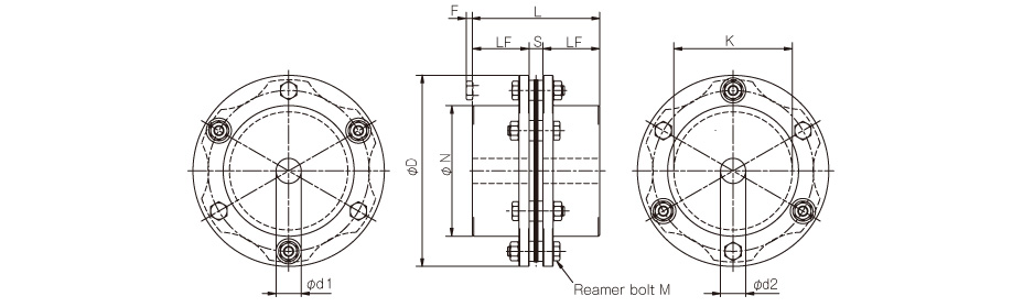
| Model | d1, d2 | D | N | L | LF | S | F | K | M | ||
|---|---|---|---|---|---|---|---|---|---|---|---|
| Pilot bore | Min. | Max. | |||||||||
| SFH-150S | 20 | 22 | 70 | 152 | 104 | 101 | 45 | 11 | 5 | 94 | 6-M8×36 |
| SFH-170S | 25 | 28 | 80 | 178 | 118 | 124 | 55 | 14 | 6 | 108 | 6-M10×45 |
| SFH-190S | 30 | 32 | 85 | 190 | 126 | 145 | 65 | 15 | 10 | 116 | 6-M12×54 |
| SFH-210S | 35 | 38 | 90 | 210 | 130 | 165 | 75 | 15 | 8 | 124 | 6-M16×60 |
| SFH-220S | 45 | 48 | 100 | 225 | 144 | 200 | 90 | 20 | -2 | 132 | 6-M16×60 |
| SFH-260S | 50 | 55 | 115 | 262 | 166 | 223 | 100 | 23 | 11 | 150 | 6-M20×80 |
*Pilot bores are to be drilled into the part. See the standard hole-drilling standards for information on bore drilling.
*The nominal diameter of the reamer bolt is equal to the quantity minus the nominal diameter of the screw threads times the nominal length.

Specifications SFH-□S-□K-□K
| Model | Rated torque [N・m] | Misalignment | Max. rotation speed [min-1] | Torsional stiffness [N・m/rad] | Axial stiffness[N/mm] | Moment of inertia [kg・m2] | Mass [kg] | |
|---|---|---|---|---|---|---|---|---|
| Angular [°] | Axial [mm] | |||||||
| SFH-150S | 1000 | 1 | ±0.4 | 5900 | 1500000 | 244 | 25.14×10⁻³ | 8.95 |
| SFH-170S | 1300 | 1 | ±0.5 | 5100 | 2840000 | 224 | 47.90×10⁻³ | 12.53 |
| SFH-190S | 2000 | 1 | ±0.5 | 4700 | 3400000 | 244 | 60.40×10⁻³ | 14.21 |
| SFH-210S | 4000 | 1 | ±0.55 | 4300 | 4680000 | 508 | 80.50×10⁻³ | 16.12 |
*Max. rotation speed does not take into account dynamic balance.
*The moment of inertia and mass in the table are measured for the maximum bore diameter.
Dimensions SFH-□S-□K-□K
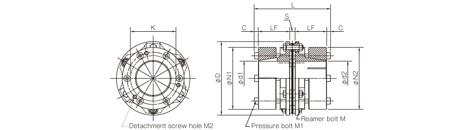
| Model | D | L | d1, d2 | N1, N2 | LF | S | C | K | M | M1 | M2 |
|---|---|---|---|---|---|---|---|---|---|---|---|
| SFH-150S | 152 | 157 | 38, 40, 42, 45, 50 | 108 | 65 | 11 | 8 | 94 | 6-M8×36 | 6-M8×60 | 3-M8 |
| 55, 56, 60, 65, 70 | 128 | ||||||||||
| SFH-170S | 178 | 160 | 38, 40, 42, 45, 50 | 108 | 65 | 14 | 8 | 108 | 6-M10×45 | 6-M8×60 | 3-M8 |
| 55, 56, 60, 65, 70 | 128 | ||||||||||
| 75, 80 | 148 | ||||||||||
| SFH-190S | 190 | 175 | 38, 40, 42, 45, 50 | 108 | 70 | 15 | 10 | 116 | 6-M12×54 | 6-M10×65 | 3-M10 |
| 55, 56, 60, 65, 70 | 128 | ||||||||||
| 75, 80, 85 | 148 | ||||||||||
| SFH-210S | 210 | 181 | 38, 40, 42, 45, 50 | 108 | 73 | 15 | 10 | 124 | 6-M16×60 | 6-M10×65 | 3-M10 |
| 55, 56, 60, 65, 70 | 128 | ||||||||||
| 75, 80, 85, 90 | 148 |
*The nominal diameters of each bolt and tap are equal to the quantity minus the nominal diameter of the screw threads times the nominal length. The quantities for the pressure bolt M1 and detachment screw hole M2 are quantities for the hub on one side.
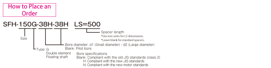
Standard bore diameter combinations
| Model | Standard bore diameters d1, d2 [mm] | ||||||||||||||
|---|---|---|---|---|---|---|---|---|---|---|---|---|---|---|---|
| 38 | 40 | 42 | 45 | 48 | 50 | 55 | 56 | 60 | 65 | 70 | 75 | 80 | 85 | 90 | |
| SFH-150S | ● | ● | ● | ● | ● | ● | ● | ● | ● | ● | ● | ||||
| SFH-170S | 1100 | 1200 | 1250 | ● | ● | ● | ● | ● | ● | ● | ● | ● | ● | ||
| SFH-190S | 1800 | 1900 | ● | ● | ● | ● | ● | ● | ● | ● | ● | ● | ● | ● | |
| SFH-210S | 1800 | 1900 | 2000 | 2150 | 2300 | 2400 | 2600 | 2650 | 2850 | 3100 | 3350 | 3600 | 3800 | ● | ● |
*The bore diameters marked with ● or numbers are supported as standard bore diameter.
*Bore diameters whose fields contain numbers are restricted in their rated torque by the holding power of the shaft connection component because the bore diameter is small. The numbers indicate the rated torque value [N·m].

SFH G Types
Specifications SFH-□G
| Model | Rated torque [N・m] | Misalignment | Max. rotation speed [min-1] | Torsional stiffness [N・m/rad] | Axial stiffness[N/mm] | Moment of inertia [kg・m2] | Mass [kg] | ||
|---|---|---|---|---|---|---|---|---|---|
| Parallel [mm] | Angular [°] | Axial [mm] | |||||||
| SFH-150G | 1000 | 1.4 | 1 (On one side) | ±0.8 | 5900 | 750000 | 122 | 21.87×10⁻³ | 8.72 |
| SFH-170G | 1300 | 1.6 | 1 (On one side) | ±1.0 | 5100 | 1420000 | 112 | 51.07×10⁻³ | 13.94 |
| SFH-190G | 2000 | 2.0 | 1 (On one side) | ±1.0 | 4700 | 1700000 | 122 | 81.58×10⁻³ | 19.51 |
| SFH-210G | 4000 | 2.1 | 1 (On one side) | ±1.1 | 4300 | 2340000 | 254 | 125.50×10⁻³ | 24.26 |
| SFH-220G | 5000 | 2.3 | 1 (On one side) | ±1.2 | 4000 | 2970000 | 224 | 176.91×10⁻³ | 30.27 |
| SFH-260G | 8000 | 2.9 | 1 (On one side) | ±1.4 | 3400 | 5390000 | 306 | 433.47×10⁻³ | 53.11 |
*Max. rotation speed does not take into account dynamic balance.
*The moment of inertia and mass are measured for the maximum bore diameter.
Dimensions SFH-□G
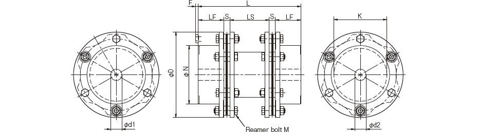
| Model | d1, d2 | D | N | L | LF | LS | S | F | K | M | ||
|---|---|---|---|---|---|---|---|---|---|---|---|---|
| Pilot bore | Min. | Max. | ||||||||||
| SFH-150G | 20 | 22 | 70 | 152 | 104 | 182 | 45 | 70 | 11 | 5 | 94 | 12-M8×36 |
| SFH-170G | 25 | 28 | 80 | 178 | 118 | 218 | 55 | 80 | 14 | 6 | 108 | 12-M10×45 |
| SFH-190G | 30 | 32 | 85 | 190 | 126 | 260 | 65 | 100 | 15 | 10 | 116 | 12-M12×54 |
| SFH-210G | 35 | 38 | 90 | 210 | 130 | 290 | 75 | 110 | 15 | 8 | 124 | 12-M16×60 |
| SFH-220G | 45 | 48 | 100 | 225 | 144 | 335 | 90 | 115 | 20 | -2 | 132 | 12-M16×60 |
| SFH-260G | 50 | 55 | 115 | 262 | 166 | 391 | 100 | 145 | 23 | 11 | 150 | 12-M20×80 |
*Pilot bores are to be drilled into the part. See the standard hole-drilling standards for information on bore drilling.
*If you require a product with an LS dimension other than that above, contact Miki Pulley with your required dimension [mm]. Please contact Miki Pulley for assistance if LS ≧ 1000.
*The nominal diameter of the reamer bolt is equal to the quantity minus the nominal diameter of the screw threads times the nominal length.
Dimensions for Vertical Applications with Max. LS Dimensions SFH-□G-□K-□K
| Model | LS [mm] |
|---|---|
| SFH-150G | 1100 |
| SFH-170G | 800 |
| SFH-190G | 900 |
| SFH-210G | 2000 |
| SFH-220G | 1900 |
| SFH-260G | 2500 |
*When considering vertical use and the LS dimension is greater than that in the above table, consult Miki Pulley.
Specifications SFH-□G-□K-□K
| Model | Rated torque [N・m] | Misalignment | Max. rotation speed [min-1] | Torsional stiffness ([N・m]/rad) | Axial stiffness[N/mm] | Moment of inertia [kg・m2] | Mass [kg] | ||
|---|---|---|---|---|---|---|---|---|---|
| Parallel [mm] | Angular [°] | Axial [mm] | |||||||
| SFH-150G | 1000 | 1.4 | 1 (On one side) | ±0.8 | 5900 | 750000 | 122 | 34.41×10⁻³ | 12.96 |
| SFH-170G | 1300 | 1.6 | 1 (On one side) | ±1.0 | 5100 | 1420000 | 112 | 72.09×10⁻³ | 18.95 |
| SFH-190G | 2000 | 2.0 | 1 (On one side) | ±1.0 | 4700 | 1700000 | 122 | 98.15×10⁻³ | 23.14 |
| SFH-210G | 4000 | 2.1 | 1 (On one side) | ±1.1 | 4300 | 2340000 | 254 | 137.53×10⁻³ | 26.61 |
*Max. rotation speed does not take into account dynamic balance.
*The moment of inertia and mass in the table are measured for the maximum bore diameter.
Dimensions SFH-□G-□K-□K

| Model | D | L | d1, d2 | N1, N2 | LF | LS | S | C | K | M | M1 | M2 |
|---|---|---|---|---|---|---|---|---|---|---|---|---|
| SFH-150G | 152 | 238 | 38, 40, 42, 45, 50 | 108 | 65 | 70 | 11 | 8 | 94 | 12-M8×36 | 6-M8×60 | 3-M8 |
| 55, 56, 60, 65, 70 | 128 | |||||||||||
| SFH-170G | 178 | 254 | 38, 40, 42, 45, 50 | 108 | 65 | 80 | 14 | 8 | 108 | 12-M10×45 | 6-M8×60 | 3-M8 |
| 55, 56, 60, 65, 70 | 128 | |||||||||||
| 75, 80 | 148 | |||||||||||
| SFH-190G | 190 | 290 | 38, 40, 42, 45, 50 | 108 | 70 | 100 | 15 | 10 | 116 | 12-M12×54 | 6-M10×65 | 3-M10 |
| 55, 56, 60, 65, 70 | 128 | |||||||||||
| 75, 80, 85 | 148 | |||||||||||
| SFH-210G | 210 | 306 | 38, 40, 42, 45, 50 | 108 | 73 | 110 | 15 | 10 | 124 | 12-M16×60 | 6-M10×65 | 3-M10 |
| 55, 56, 60, 65, 70 | 128 | |||||||||||
| 75, 80, 85, 90 | 148 |
*If you require a product with an LS dimension other than that above, contact Miki Pulley with your required dimension [mm]. Please contact Miki Pulley for assistance if LS ≧ 1000.
*The nominal diameters of each bolt and tap are equal to the quantity minus the nominal diameter of the screw threads times the nominal length. The quantities for the pressure bolt M1 and detachment screw hole M2 are quantities for the hub on one side.
Combination of Standard Bore Diameter
| Model | Standard bore diameters d1, d2 [mm] | ||||||||||||||
|---|---|---|---|---|---|---|---|---|---|---|---|---|---|---|---|
| 38 | 40 | 42 | 45 | 48 | 50 | 55 | 56 | 60 | 65 | 70 | 75 | 80 | 85 | 90 | |
| SFH-150G | ● | ● | ● | ● | ● | ● | ● | ● | ● | ● | ● | ||||
| SFH-170G | 1100 | 1200 | 1250 | ● | ● | ● | ● | ● | ● | ● | ● | ● | ● | ||
| SFH-190G | 1800 | 1900 | ● | ● | ● | ● | ● | ● | ● | ● | ● | ● | ● | ● | |
| SFH-210G | 1800 | 1900 | 2000 | 2150 | 2300 | 2400 | 2600 | 2650 | 2850 | 3100 | 3350 | 3600 | 3800 | ● | ● |
*The bore diameters marked with ● or numbers are supported as standard bore diameter.
*Bore diameters whose fields contain numbers are restricted in their rated torque by the holding power of the shaft connection component because the bore diameter is small. The numbers indicate the rated torque value [N·m].
Dimensions for Vertical Applications with Max. LS Dimensions
| Model | LS [mm] |
|---|---|
| SFH-150G | 1100 |
| SFH-170G | 800 |
| SFH-190G | 900 |
| SFH-210G | 2000 |
*When considering vertical use and the LS dimension is greater than that in the above table, consult Miki Pulley.
Standard Hole-drilling Standards
| Models compliant with the old JIS standards (Class 2) | Models compliant with the new JIS standards | Models compliant with the new motor standards | ||||||||||||
|---|---|---|---|---|---|---|---|---|---|---|---|---|---|---|
| Nominal bore diameter | Bore diameter (d1, d2) | Keyway width (W1, W2) | Keyway height (T1, T2) | Set screw hole (M) | Nominal bore diameter | Bore diameter (d1, d2) | Keyway width (W1, W2) | Keyway height (T1, T2) | Set screw hole (M) | Nominal bore diameter | Bore diameter (d1, d2) | Keyway width (W1, W2) | Keyway height (T1, T2) | Set screw hole (M) |
| Tolerance | SFM DS | E9 | — | Tolerance | H7 | H9 | — | Tolerance | G7, F7 | H9 | — | |||
| 22 | 22+0.0210 | 7+0.061+0.025 | 25.0+0.30 | 2-M6 | 22H | 22+0.0210 | 6+0.0300 | 24.8+0.30 | 2-M5 | — | — | — | — | — |
| 24 | 24+0.0210 | 7+0.061+0.025 | 27.0+0.30 | 2-M6 | 24H | 24+0.0210 | 8+0.0360 | 27.3+0.30 | 2-M6 | 24N | 24+0.028+0.007 | 8+0.0360 | 27.3+0.30 | 2-M6 |
| 25 | 25+0.0210 | 7+0.061+0.025 | 28.0+0.30 | 2-M6 | 25H | 25+0.0210 | 8+0.0360 | 28.3+0.30 | 2-M6 | — | — | — | — | — |
| 28 | 28+0.0210 | 7+0.061+0.025 | 31.0+0.30 | 2-M6 | 28H | 28+0.0210 | 8+0.0360 | 31.3+0.30 | 2-M6 | 28N | 28+0.028+0.007 | 8+0.0360 | 31.3+0.30 | 2-M6 |
| 30 | 30+0.0210 | 7+0.061+0.025 | 33.0+0.30 | 2-M6 | 30H | 30+0.0210 | 8+0.0360 | 33.3+0.30 | 2-M6 | — | — | — | — | — |
| 32 | 32+0.0250 | 10+0.061+0.025 | 35.5+0.30 | 2-M8 | 32H | 32+0.0250 | 10+0.0360 | 35.3+0.30 | 2-M8 | — | — | — | — | — |
| 35 | 35+0.0250 | 10+0.061+0.025 | 38.5+0.30 | 2-M8 | 35H | 35+0.0250 | 10+0.0360 | 38.3+0.30 | 2-M8 | — | — | — | — | — |
| 38 | 38+0.0250 | 10+0.061+0.025 | 41.5+0.30 | 2-M8 | 38H | 38+0.0250 | 10+0.0360 | 41.3+0.30 | 2-M8 | 38N | 38+0.050+0.025 | +0.036010 | 41.3+0.30 | 2-M8 |
| 40 | 40+0.0250 | 10+0.061+0.025 | 43.5+0.30 | 2-M8 | 40H | 40+0.0250 | 12+0.0430 | 43.3+0.30 | 2-M8 | — | — | — | — | — |
| 42 | 42+0.0250 | 12+0.061+0.025 | 45.5+0.30 | 2-M8 | 42H | 42+0.0250 | 12+0.0430 | 45.3+0.30 | 2-M8 | 42N | 42+0.050+0.025 | 12+0.0430 | 45.3+0.30 | 2-M8 |
| 45 | 45+0.0250 | 12+0.061+0.025 | 48.5+0.30 | 2-M8 | 45H | 45+0.0250 | 14+0.0430 | 48.8+0.30 | 2-M10 | — | — | — | — | — |
| 48 | 48+0.0250 | 12+0.061+0.025 | 51.5+0.30 | 2-M8 | 48H | 48+0.0250 | 14+0.0430 | 51.8+0.30 | 2-M10 | 48N | 48+0.050+0.025 | 14+0.0430 | 51.8+0.30 | 2-M10 |
| 50 | 50+0.0250 | 12+0.061+0.025 | 53.5+0.30 | 2-M8 | 50H | 50+0.0250 | 14+0.0430 | 53.8+0.30 | 2-M10 | — | — | — | — | — |
| 55 | 55+0.0300 | 15+0.075+0.032 | 60.0+0.30 | 2-M10 | 55H | 55+0.0300 | 16+0.0430 | 59.3+0.30 | 2-M10 | 55N | 55+0.060+0.030 | 16+0.0430 | 59.3+0.30 | 2-M10 |
| 56 | 56+0.0300 | 15+0.075+0.032 | 61.0+0.30 | 2-M10 | 56H | 56+0.0300 | 16+0.0430 | 60.3+0.30 | 2-M10 | — | — | — | — | — |
| 60 | 60+0.0300 | 15+0.075+0.032 | 65.0+0.30 | 2-M10 | 60H | 60+0.0300 | 18+0.0430 | 64.4+0.30 | 2-M10 | 60N | 60+0.060+0.030 | 18+0.0430 | 64.4+0.30 | 2-M10 |
| 65 | 65+0.0300 | 18+0.075+0.032 | 71.0+0.30 | 2-M10 | 65H | 65+0.0300 | 18+0.0430 | 69.4+0.30 | 2-M10 | 65N | 65+0.060+0.030 | 18+0.0430 | 69.4+0.30 | 2-M10 |
| 70 | 70+0.0300 | 18+0.075+0.032 | 76.0+0.30 | 2-M10 | 70H | 70+0.0300 | 20+0.0520 | 74.9+0.50 | 2-M10 | — | — | — | — | — |
| 75 | 75+0.0300 | 20+0.092+0.040 | 81.0+0.50 | 2-M10 | 75H | 75+0.0300 | 20+0.0520 | 79.9+0.50 | 2-M10 | 75N | 75+0.060+0.030 | 20+0.0520 | 79.9+0.50 | 2-M10 |
| 80 | 80+0.0300 | 20+0.092+0.040 | 86.0+0.50 | 2-M10 | 80H | 80+0.0300 | 22+0.0520 | 85.4+0.50 | 2-M12 | — | — | — | — | — |
| 85 | 85+0.0350 | 24+0.092+0.040 | 93.0+0.50 | 2-M12 | 85H | 85+0.0350 | 22+0.0520 | 90.4+0.50 | 2-M12 | 85N | 85+0.071+0.035 | 22+0.0520 | 90.4+0.50 | 2-M12 |
| 90 | 90+0.0350 | 24+0.092+0.040 | 98.0+0.50 | 2-M12 | 90H | 90+0.0350 | 25+0.0520 | 95.4+0.50 | 2-M12 | — | — | — | — | — |
| 95 | 95+0.0350 | 24+0.092+0.040 | 103.0+0.50 | 2-M12 | 95H | 95+0.0350 | 25+0.0520 | 100.4+0.50 | 2-M12 | 95N | 95+0.071+0.035 | 25+0.0520 | 100.4+0.50 | 2-M12 |
| 100 | 100+0.0350 | 28+0.092+0.040 | 109.0+0.50 | 2-M12 | 100H | 100+0.0350 | 28+0.0520 | 106.4+0.50 | 2-M12 | — | — | — | — | — |
| 115 | 115+0.0350 | 32+0.112+0.050 | 125.0+0.50 | 2-M12 | 115H | 115+0.0350 | 32+0.0520 | 122.4+0.50 | 2-M12 | — | — | — | — | — |


