Miki Pulley SFM Models

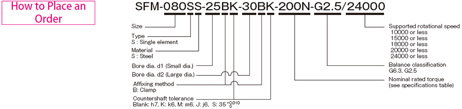
Specifications – Clamping
| Model | Rated torque [N・m] |
Misalignment | Max. rotation speed [min-1] |
Torsional stiffness [N・m/rad] |
Axial stiffness [N/mm] |
Moment of inertia [kg・m2] |
Mass [kg] |
||
|---|---|---|---|---|---|---|---|---|---|
| Parallel [mm] |
Angular [°] |
Axial [mm] |
|||||||
| SFM-060SS-□B-□B-60N | 60 | 0.02 | 1 | ±0.3 | 24000 | 104000 | 399 | 0.22×10⁻³ | 0.52 |
| SFM-060SS-□B-□B-80N | 80 | 0.02 | 1 | ±0.3 | 24000 | 104000 | 399 | 0.23×10⁻³ | 0.49 |
| SFM-070SS-□B-□B-90N | 90 | 0.02 | 1 | ±0.5 | 24000 | 240000 | 484 | 0.40×10⁻³ | 0.72 |
| SFM-070SS-□B-□B-100N | 100 | 0.02 | 1 | ±0.5 | 24000 | 240000 | 484 | 0.42×10⁻³ | 0.67 |
| SFM-080SS-□B-□B-150N | 150 | 0.02 | 1 | ±0.5 | 24000 | 120000 | 96 | 0.79×10⁻³ | 1.04 |
| SFM-080SS-□B-□B-200N | 200 | 0.02 | 1 | ±0.5 | 24000 | 310000 | 546 | 1.25×10⁻³ | 1.40 |
| SFM-090SS-□B-□B-250N | 250 | 0.02 | 1 | ±0.6 | 24000 | 520000 | 321 | 1.54×10⁻³ | 1.62 |
| SFM-090SS-□B-□B-300N | 300 | 0.02 | 1 | ±0.6 | 24000 | 520000 | 321 | 1.58×10⁻³ | 1.53 |
| SFM-100SS-□B-□B-450N | 450 | 0.02 | 1 | ±0.65 | 20000 | 740000 | 540 | 3.27×10⁻³ | 2.53 |
| SFM-120SS-□B-□B-600N | 600 | 0.02 | 1 | ±0.8 | 20000 | 970000 | 360 | 6.90×10⁻³ | 3.78 |
*Torsional stiffness values given are calculated for the element alone.
*The moment of inertia and mass are measured for the maximum bore diameter.
Dimensions – Clamping
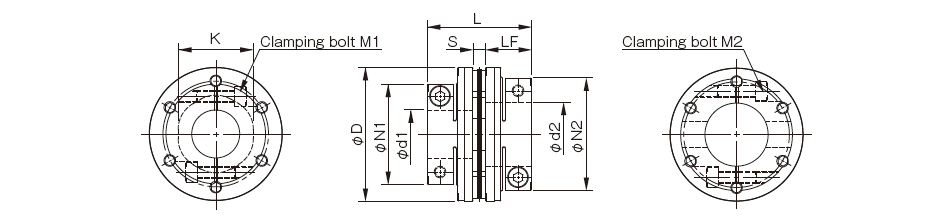
| Model | d1[mm] | d2[mm] | D[mm] | L[mm] | N1・N2[mm] | LF[mm] | S[mm] | K[mm] | M1・M2 Quantity -Nominal dia. |
M1・M2 Tightening torque [N・m] |
|---|---|---|---|---|---|---|---|---|---|---|
| SFM-060SS-□B-□B-60N | 12・14・15・16・17・18・19 | 12・14・15・16・17・18・19・20・22 | 58 | 53.4 | 44 | 24 | 5.4 | 32 | 2-M6 | 14 |
| – | 24・25・28 | 58 | 53.4 | 48 | 24 | 5.4 | 32 | 2-M5 | 7 | |
| – | 30 | 58 | 53.4 | 52 | 24 | 5.4 | 32 | 2-M5 | 7 | |
| SFM-060SS-□B-□B-80N | 20・22 | 20・22 | 58 | 53.4 | 44 | 24 | 5.4 | 32 | 2-M6 | 14 |
| 24・25・28 | 24・25・28 | 58 | 53.4 | 48 | 24 | 5.4 | 32 | 2-M5 | 7 | |
| 30 | 30 | 58 | 53.4 | 52 | 24 | 5.4 | 32 | 2-M5 | 7 | |
| SFM-070SS-□B-□B-90N | 18・19 | 18・19・20・22・24・25 | 68 | 55.9 | 47 | 25 | 5.9 | 38 | 2-M6 | 14 |
| – | 28・30・32・35 | 68 | 55.9 | 56 | 25 | 5.9 | 38 | 2-M6 | 14 | |
| SFM-070SS-□B-□B-100N | 20・22・24・25 | 20・22・24・25 | 68 | 55.9 | 47 | 25 | 5.9 | 38 | 2-M6 | 14 |
| 28・30・32・35 | 28・30・32・35 | 68 | 55.9 | 56 | 25 | 5.9 | 38 | 2-M6 | 14 | |
| SFM-080SS-□B-□B-150N | 22・24・25 | 22・24・25 | 78 | 68.3 | 53 | 30 | 8.3 | 37 | 2-M8 | 34 |
| 28・30・32・35 | 28・30・32・35 | 78 | 68.3 | 56 | 30 | 8.3 | 37 | 2-M6 | 14 | |
| SFM-080SS-□B-□B-200N | 22・24・25 | 22・24・25 | 78 | 67.7 | 53 | 30 | 7.7 | 42 | 2-M8 | 34 |
| 28・30・32・35 | 28・30・32・35 | 78 | 67.7 | 70 | 30 | 7.7 | 42 | 2-M8 | 34 | |
| 38 | 38 | 78 | 67.7 | 74 | 30 | 7.7 | 42 | 2-M8 | 34 | |
| SFM-090SS-□B-□B-250N | 25・28 | 25・28・30・32 | 88 | 68.3 | 66 | 30 | 8.3 | 50 | 2-M8 | 34 |
| – | 35・38・40・42 | 88 | 68.3 | 74 | 30 | 8.3 | 50 | 2-M8 | 34 | |
| SFM-090SS-□B-□B-300N | 30・32 | 30・32 | 88 | 68.3 | 66 | 30 | 8.3 | 50 | 2-M8 | 34 |
| 35・38・40・42 | 35・38・40・42 | 88 | 68.3 | 74 | 30 | 8.3 | 50 | 2-M8 | 34 | |
| SFM-100SS-□B-□B-450N | 32・35・38・40・42・45・48 | 32・35・38・40・42・45・48 | 98 | 90.2 | 84 | 40 | 10.2 | 56 | 2-M10 | 68 |
| SFM-120SS-□B-□B-600N | 32・35・38・40・42・45 | 32・35・38・40・42・45 | 118 | 90.2 | 84 | 40 | 10.2 | 68 | 2-M10 | 68 |
| 48・50・55 | 48・50・55 | 118 | 90.2 | 100 | 40 | 10.2 | 68 | 2-M10 | 68 |
* Nominal diameter of clamping bolt M1/M2 is given as number of bolts – nominal diameter, and the number is the number for one hub.
Standard bore diameter combinations – Clamping
| Model | Standard bore diameter d1・d2[mm] | ||||||||||||||||||||||
|---|---|---|---|---|---|---|---|---|---|---|---|---|---|---|---|---|---|---|---|---|---|---|---|
| Nominal diameter | 12 | 14 | 15 | 16 | 17 | 18 | 19 | 20 | 22 | 24 | 25 | 28 | 30 | 32 | 35 | 38 | 40 | 42 | 45 | 48 | 50 | 55 | |
| SFM-060SS-□B-□B-60N | d1 | ● | ● | ● | ● | ● | ● | ● | |||||||||||||||
| d2 | ● | ● | ● | ● | ● | ● | ● | ● | ● | ● | ● | ● | ● | ||||||||||
| SFM-060SS-□B-□B-80N | d1 | ● | ● | ● | ● | ● | ● | ||||||||||||||||
| d2 | ● | ● | ● | ● | ● | ● | |||||||||||||||||
| SFM-070SS-□B-□B-90N | d1 | ● | ● | ||||||||||||||||||||
| d2 | ● | ● | ● | ● | ● | ● | ● | ● | ● | ● | |||||||||||||
| SFM-070SS-□B-□B-100N | d1 | ● | ● | ● | ● | ● | ● | ● | ● | ||||||||||||||
| d2 | ● | ● | ● | ● | ● | ● | ● | ● | |||||||||||||||
| SFM-080SS-□B-□B-150N | d1 | ● | ● | ● | ● | ● | ● | ● | |||||||||||||||
| d2 | ● | ● | ● | ● | ● | ● | ● | ||||||||||||||||
| SFM-080SS-□B-□B-200N | d1 | ● | ● | ● | ● | ● | ● | ● | ● | ||||||||||||||
| d2 | ● | ● | ● | ● | ● | ● | ● | ● | |||||||||||||||
| SFM-090SS-□B-□B-250N | d1 | ● | ● | ||||||||||||||||||||
| d2 | ● | ● | ● | ● | ● | ● | ● | ● | |||||||||||||||
| SFM-090SS-□B-□B-300N | d1 | ● | ● | ● | ● | ● | ● | ||||||||||||||||
| d2 | ● | ● | ● | ● | ● | ● | |||||||||||||||||
| SFM-100SS-□B-□B-450N | d1 | ● | ● | ● | ● | ● | ● | ● | |||||||||||||||
| d2 | ● | ● | ● | ● | ● | ● | ● | ||||||||||||||||
| SFM-120SS-□B-□B-600N | d1 | ● | ● | ● | ● | ● | ● | ● | ● | ● | |||||||||||||
| d2 | ● | ● | ● | ● | ● | ● | ● | ● | ● | ||||||||||||||
* The bore diameters marked with ● are supported as standard bore diameter.
Balance correction – Clamping
| Model(Size) | Balance classification | Supported rotational speed[min-1] | ||||
|---|---|---|---|---|---|---|
| 10000 or less | 15000 or less | 18000 or less | 20000 or less | 24000 or less | ||
| SFM-060SS | G6.3・G2.5 | ● | ● | ● | ● | ● |
| SFM-070SS | G6.3・G2.5 | ● | ● | ● | ● | ● |
| SFM-080SS | G6.3・G2.5 | ● | ● | ● | ● | ● |
| SFM-090SS | G6.3・G2.5 | ● | ● | ● | ● | ● |
| SFM-100SS | G6.3・G2.5 | ● | ● | ● | ● | |
| SFM-120SS | G6.3・G2.5 | ● | ● | ● | ● | |
* We will perform balance correction for supported rotational speeds marked with ● .
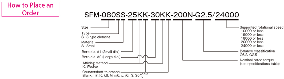
Specifications – Wedge Coupling
| Model | Rated torque [N・m] |
Misalignment | Max. rotation speed [min-1] |
Torsional stiffness [N・m/rad] |
Axial stiffness [N/mm] |
Moment of inertia [kg・m2] |
Mass [kg] |
||
|---|---|---|---|---|---|---|---|---|---|
| Parallel [mm] |
Angular [°] |
Axial [mm] |
|||||||
| SFM-070SS-□K-□K-100N | 100 | 0.02 | 1 | ±0.5 | 24000 | 240000 | 484 | 0.66×10⁻³ | 0.92 |
| SFM-080SS-□K-□K-150N | 150 | 0.02 | 1 | ±0.5 | 24000 | 120000 | 96 | 1.21×10⁻³ | 1.03 |
| SFM-080SS-□K-□K-200N | 200 | 0.02 | 1 | ±0.5 | 24000 | 310000 | 546 | 1.11×10⁻³ | 1.26 |
| SFM-090SS-□K-□K-300N | 300 | 0.02 | 1 | ±0.6 | 24000 | 520000 | 321 | 1.75×10⁻³ | 1.48 |
| SFM-100SS-□K-□K-450N | 450 | 0.02 | 1 | ±0.65 | 20000 | 740000 | 540 | 2.56×10⁻³ | 1.87 |
| SFM-120SS-□K-□K-600N | 600 | 0.02 | 1 | ±0.8 | 20000 | 970000 | 360 | 5.33×10⁻³ | 2.50 |
| SFM-140SS-□K-□K-800N | 800 | 0.02 | 1 | ±1.0 | 20000 | 1400000 | 360 | 10.28×10⁻³ | 4.66 |
| SFM-140SS-□K-□K-1000N | 1000 | 0.02 | 1 | ±1.0 | 20000 | 1400000 | 360 | 14.70×10⁻³ | 5.01 |
*Torsional stiffness values given are calculated for the element alone.
*The moment of inertia and mass are measured for the maximum bore diameter.
Dimensions – Wedge Coupling
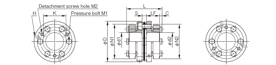
| Model | d1[mm] | d2[mm] | D[mm] | L[mm] | N1・N2[mm] | LF[mm] | S[mm] | C[mm] | K[mm] | H[mm] | M1 Quantity -Nominal dia. |
M1 Tightening torque [N・m] |
M2 Quantity -Nominal dia. |
|---|---|---|---|---|---|---|---|---|---|---|---|---|---|
| SFM-070SS-□K-□K-100N | 18・19 | 18・19 | 68 | 62.9 | 53 | 23.5 | 5.9 | 5 | 38 | 3-5.1 | 6-M6 | 10 | 3-M6 |
| 20・22・24・25 | 20・22・24・25 | 58 | |||||||||||
| 28・30 | 28・30 | 63 | |||||||||||
| 32・35 | 32・35 | 68 | |||||||||||
| SFM-080SS-□K-□K-150N | 22・24・25 | 22・24・25 | 78 | 69.3 | 58 | 25.5 | 8.3 | 5 | 37 | 4-5.1 | 4-M6 | 10 | 2-M6 |
| 28・30 | 28・30 | 63 | |||||||||||
| 32・35 | 32・35 | 68 | |||||||||||
| – | 38 | 73 | |||||||||||
| SFM-080SS-□K-□K-200N | 22・24・25 | 22・24・25 | 78 | 68.7 | 58 | 25.5 | 7.7 | 5 | 42 | 3-5.1 | 6-M6 | 10 | 3-M6 |
| 28・30 | 28・30 | 63 | |||||||||||
| 32・35 | 32・35 | 68 | |||||||||||
| 38 | 38 | 73 | |||||||||||
| SFM-090SS-□K-□K-300N | 28・30 | 28・30 | 88 | 69.3 | 63 | 25.5 | 8.3 | 5 | 50 | 3-6.8 | 6-M6 | 10 | 3-M6 |
| 32・35 | 32・35 | 68 | |||||||||||
| 38・40・42 | 38・40・42 | 73 | |||||||||||
| 45 | 45 | 78 | |||||||||||
| 48 | 48 | 83 | |||||||||||
| SFM-100SS-□K-□K-450N | 32・35 | 32・35 | 98 | 75.2 | 68 | 27.5 | 10.2 | 5 | 56 | 3-6.8 | 6-M6 | 10 | 3-M6 |
| 38・40・42 | 38・40・42 | 73 | |||||||||||
| 45 | 45 | 78 | |||||||||||
| 48・50 | 48・50 | 83 | |||||||||||
| SFM-120SS-□K-□K-600N | 35 | 35 | 118 | 75.2 | 68 | 27.5 | 10.2 | 5 | 68 | 3-6.8 | 6-M6 | 10 | 3-M6 |
| 38・40・42 | 38・40・42 | 73 | |||||||||||
| 45 | 45 | 78 | |||||||||||
| 48・50・52 | 48・50・52 | 83 | |||||||||||
| 55 | 55 | 88 | |||||||||||
| 60・62・65 | 60・62・65 | 98 | |||||||||||
| – | 70 | 108 | |||||||||||
| SFM-140SS-□K-□K-800N | 35・38 | 35・38 | 138 | 94.6 | 83 | 36.5 | 10.6 | 5.5 | 78 | 3-8.6 | 6-M8 | 24 | 3-M8 |
| 40・42・45 | 40・42・45 | 88 | |||||||||||
| – | 48・50・52 | 98 | |||||||||||
| 55・60 | 108 | ||||||||||||
| 62・65・70 | 118 | ||||||||||||
| 75・80 | 128 | ||||||||||||
| SFM-140SS-□K-□K-1000N | 48・50・52 | 48・50・52 | 138 | 94.6 | 98 | 36.5 | 10.6 | 5.5 | 78 | 3-8.6 | 6-M8 | 24 | 3-M8 |
| 55・60 | 55・60 | 108 | |||||||||||
| 62・65・70 | 62・65・70 | 118 | |||||||||||
| 75 | 75・80 | 128 |
* The nominal diameters of the pressure bolt M1 and detachment screw hole M2 are equal to the quantity minus the nominal diameter of the screw threads. The quantities of H, M1 and M2 are the same as the quantity for a hub on one side.
Standard Bore Diameter – Wedge Coupling
| Model | Standard bore diameter d1・d2[mm] | ||||||||||||||||||||||||
|---|---|---|---|---|---|---|---|---|---|---|---|---|---|---|---|---|---|---|---|---|---|---|---|---|---|
| Nominal diameter | 18 | 19 | 20 | 22 | 24 | 25 | 28 | 30 | 32 | 35 | 38 | 40 | 42 | 45 | 48 | 50 | 52 | 55 | 60 | 62 | 65 | 70 | 75 | 80 | |
| SFM-070SS-□K-□K-100N | d1 | ● | ● | ● | ● | ● | ● | ● | ● | ● | ● | ||||||||||||||
| d2 | ● | ● | ● | ● | ● | ● | ● | ● | ● | ● | |||||||||||||||
| SFM-080SS-□K-□K-150N | d1 | ● | ● | ● | ● | ● | ● | ● | |||||||||||||||||
| d2 | ● | ● | ● | ● | ● | ● | ● | ● | |||||||||||||||||
| SFM-080SS-□K-□K-200N | d1 | ● | ● | ● | ● | ● | ● | ● | ● | ||||||||||||||||
| d2 | ● | ● | ● | ● | ● | ● | ● | ● | |||||||||||||||||
| SFM-090SS-□K-□K-300N | d1 | ● | ● | ● | ● | ● | ● | ● | ● | ● | |||||||||||||||
| d2 | ● | ● | ● | ● | ● | ● | ● | ● | ● | ||||||||||||||||
| SFM-100SS-□K-□K-450N | d1 | ● | ● | ● | ● | ● | ● | ● | ● | ||||||||||||||||
| d2 | ● | ● | ● | ● | ● | ● | ● | ● | |||||||||||||||||
| SFM-120SS-□K-□K-600N | d1 | ● | ● | ● | ● | ● | ● | ● | ● | ● | ● | ● | ● | ||||||||||||
| d2 | ● | ● | ● | ● | ● | ● | ● | ● | ● | ● | ● | ● | ● | ||||||||||||
| SFM-140SS-□K-□K-800N | d1 | ● | ● | ● | ● | ● | |||||||||||||||||||
| d2 | ● | ● | ● | ● | ● | ● | ● | ● | ● | ● | ● | ● | ● | ● | ● | ||||||||||
| SFM-140SS-□K-□K-1000N | d1 | ● | ● | ● | ● | ● | ● | ● | ● | ● | |||||||||||||||
| d2 | ● | ● | ● | ● | ● | ● | ● | ● | ● | ● | |||||||||||||||
* The bore diameters marked with ● are supported as standard bore diameter.
Balance correction – Wedge Coupling
| Model(Size) | Balance classification | Supported rotational speed[min-1] | ||||
|---|---|---|---|---|---|---|
| 10000 or less | 15000 or less | 18000 or less | 20000 or less | 24000 or less | ||
| SFM-070SS | G6.3・G2.5 | ● | ● | ● | ● | ● |
| SFM-080SS | G6.3・G2.5 | ● | ● | ● | ● | ● |
| SFM-090SS | G6.3・G2.5 | ● | ● | ● | ● | ● |
| SFM-100SS | G6.3・G2.5 | ● | ● | ● | ● | |
| SFM-120SS | G6.3・G2.5 | ● | ● | ● | ● | |
| SFM-140SS | G6.3・G2.5 | ● | ● | ● | ● | |
* We will perform balance correction for supported rotational speeds marked with ● .