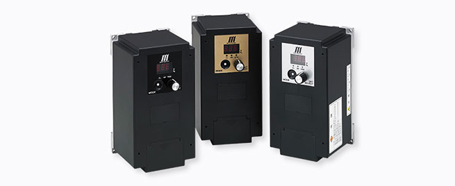
Miki Pulley BEH Models (For ultra-high-speed control)
Specifications
| Model | BEH-10G | BEH-20G | BEH-20G-1 | |
|---|---|---|---|---|
| Input voltage | AC200V ± 10% | AC200V ± 10% | AC100V ± 10% | |
| Single phase, 50/60 Hz | ||||
| Output voltage | Overexcitation voltage | Initial value 100 V, 0 to 250 V variable | ||
| Constant excitation voltage | Initial value 24 V, 0 to 250 V variable | |||
| Reverse excitation voltage | Initial value 100 V, 0 to 250 V variable | |||
| Voltage control method | PWM control | |||
| Output current | 2 A | 4 A | 4 A | |
| Applicable clutche/brake size | 02 ~ 16 | 02 ~ 32 | 02 ~ 32 | |
| MIKI PULLEY electromagnetic-actuated clutches and brakes Rated voltage DC 24 V | ||||
| Protective functions | Undervoltage protection, overvoltage protection, overcurrent protection/detection, break detection, element overheating protection, input-side fuse (20 A) | |||
| Usage environment | -10 – +50℃ / 10 – 90%RH | |||
| Mass | 0.85kg | 0.9kg | 0.9kg | |
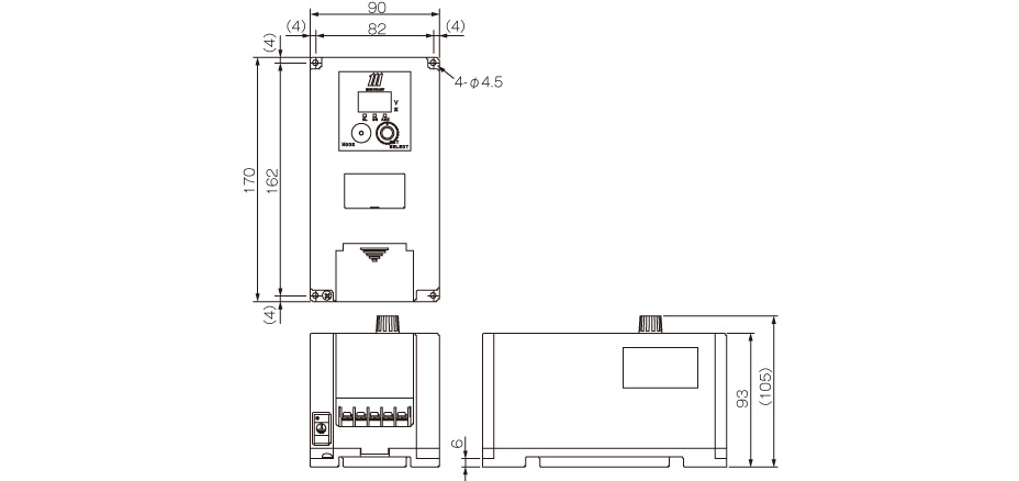
Dimensions
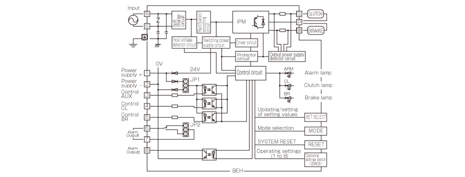
Structure
Operating Settings
| Operating settings SW (SW3) Switch No. | ON (Up) | OFF (Down) | OFF | |
|---|---|---|---|---|
| 1 | Settings/operating modes | Setup mode | Operation mode | OFF |
| 2 | Stand-alone/interlocked mode | Stand-alone mode | Interlocked mode | OFF |
| 3 | Break/overcurrent detection | Enabled | Disabled | OFF |
| 4 | Current/voltage control | Current control | Voltage control | OFF |
| 5 | Control AUX | Enabled | Disabled | OFF |
| 6 | Jog operation | Enabled | Disabled | OFF |
| 7 | Slope operation | Enabled | Disabled | OFF |
| 8 | One-shot operation | Enabled | Disabled | OFF |
Terminals and Functions
| Terminal symbol | Terminal name | Function description |
|---|---|---|
| R-S | Power supply input terminal | Connector for a commercial power supply |
| CL-P | Clutch output terminal | Connector for a clutch |
| BR-P | Brake output terminal | Connector for a brake |
| Ground | External ground terminal (third class ground or more) | |
| 1 | Power supply terminal + | Positive terminal of control power supply (shared with the internal supply’s +24 V) |
| 2 | Power supply terminal – | Negative terminal of control power supply (shared with the internal supply’s 0 V) |
| 3 | Control AUX | When operating switch 5 (AUX operation) is on, executes the operation of the conditions set in the table. |
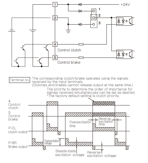
| 4 | Control clutch | Turns output between P and CL on and off. |
| 5 | Control brake | Turns output between P and BR on and off. |
| 6・7 | Alarm output 1 | A relay that operates during an alarm stop (relay output) |
| 8 | Alarm output 2 | Output operates during an alarm stop (transistor output) |
Characteristics
Operating response
The circuit construction is completely contactless, and response from signal input to output to the electromagnetic-actuated clutch or brake is fast and stable. The operating speed of the electromagnetic clutch or brake is also increased to the limit speed by the overexcitation and reverse excitation functions. This is the top-of-the-line model for electromagnetic clutch/brake power supplies. It achieves ultra-high-speed control and high precision.
Noise During Operation
The BEH models are quiet power supplies.
Electromagnetic clutches and brakes normally produce howling sounds during operation. The quiet design of BEH models eliminates such sounds.
Output Control System
You can select either Stand-alone Mode, which controls stand-alone electromagnetic clutches and brakes independently, or Interlocked Mode, which is suited to combination control of electromagnetic clutches and brakes.
There is also a diverse array of other operating modes, such as current control mode and jog mode. These are compatible with a diversity of applications.
Supply Voltage Fluctuations and Output Voltage
BEH models control output voltage to be constant even with a certain amount of supply voltage fluctuation. This ensures stable output even in locations with a bad power supply environment. Variations in electromagnetic clutch/brake response disappear.
However, overly large voltage fluctuations will be sensed as abnormal voltages and set off an alarm. To ensure proper operation, keep supply voltage fluctuation to within a range of ± 10%.
Wiring methods and timing charts
Operating mode (Operating Settings SW-2 Off)

Stand-alone operation mode (Operating Settings SW-2 On)