

Miki Pulley BES Models (For ordinary high-speed control)

Specifications
| Model | BES-20-□-1 | BES-40-□-1 | BES-20-□ | BES-40-□ |
|---|---|---|---|---|
| Input voltage | AC100V ± 10% 50/60Hz | AC100V ± 10% 50/60Hz | AC200V ± 10% 50/60Hz | AC200V ± 10% 50/60Hz |
| Output current | 2.0 A | 4.0 A | 2.0 A | 4.0 A |
| Voltage control method | PWM control | |||
| Constant excitation voltage | Adjusted for each model and size at the time of shipment | |||
| Overexcitation voltage | DC 90 V Full-wave (with AC 100 V input) | DC 180 V Full-wave (with AC 200 V input) | ||
| Overexcitation time | Adjusted for each model and size at the time of shipment | |||
| Protective functions | Input side Quick-acting fuse (5A) | |||
| Insulating resistance | DC 500 V With Megger 100 M Ω (between terminal and main body) | |||
| Dielectric strength voltage | AC 1000 V 50 Hz 1 min. (between terminal and main body) | |||
| Usage environment | -10℃ to +50℃/10% to 90% RH (with no condensation) | |||
| Mass | 0.3 kg | 0.7 kg | 0.3 kg | 0.7 kg |
*The voltage that is output is not insulated from the power supply, so shocks can result if touched.
Dimensions

Structure

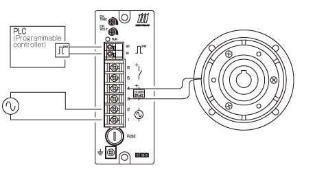
Terminals and Functions
| Terminal symbol | Terminal name | Function description |
|---|---|---|
| 1-2 | Power supply input terminal | Connector for a commercial power supply |
| 3-4 | Output terminal | Connector for an electromagnetic clutch or brake |
| 5-6 | Control terminal 1 | Output is controlled by opening and closing between terminals using a relay or the like. |
| Ground terminal | External ground terminal (third class ground or more) | |
| S1-S2 | Control terminal 2 | Output is controlled by turning the DC 24 V on and off (30 mA, smoothing power supply) |
Characteristics
Operating Response
All circuits have been made contactless, and response from signal input to output to the electromagnetic-actuated clutch or brake is fast and stable.
Energy Saving
Standby power is “zero.” Absolutely no electricity is wastefully consumed.
By combining this power supply with a MIKI PULLEY spring-actuated brake, the electricity consumption and heat generation of the springactuated brake is reduced by more than 70%, saving energy.
Noise During Operation
BES models use a quiet design, but electromagnetic clutches and brakes may produce excitation noise when operating under some mounting conditions. This noise is not abnormal and is not cause for concern.
Two Types of Control Systems
You can operate under either PLC control (which uses voltage control via programmable controllers or the like) or contactor control (which controls using relays and the like).
In the case of contactor control, however, a power controller for controlling the power supply line must be used.
Supply Voltage Fluctuations and Output Voltage
BES model power supplies are designed to operate reliably even when supply voltage fluctuates. Characteristically, however, their output voltage will rise or fall along with rises and falls of supply voltage. To fulfill electromagnetic clutch/brake performance, supply voltage fluctuations should be kept within a range of ± 10%.
Wiring Methods and Timing Charts
Wiring 1 (PLC Control)
Wiring 2 (Contactor Control)

Time Chart
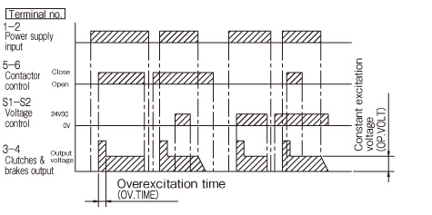
Table of Power Supply/Size Correspondence
| MIKI PULLEY electromagnetic-actuated clutch/brake size | 02 | 025 | 03 | 04 | 05 | 06 | 08 | 10 | 12 | 16 | 20 | 25 | |
|---|---|---|---|---|---|---|---|---|---|---|---|---|---|
| Nominal power supply output current | 20 | 40 | |||||||||||
| Power supply size | Excitation voltage For 24 V | 05 | 10 | 16 | 20 | 25 | |||||||
| MIKI PULLEY electromagnetic tooth clutch sizes | 12 | 13 | 15 | 21 | 23 | 25 | 31 | 32 | |
|---|---|---|---|---|---|---|---|---|---|
| Nominal power supply output current | 20 | 40 | |||||||
| Power supply size | Excitation voltage For 24 V | 51 | 52 | 53 | |||||
| MIKI PULLEY spring-actuated brake size | 01 | 02 | 03 | 04 | 05 | 06 | 08 | 10 | 12 | 14 | 16 | 18 | 20 | 25 | |
|---|---|---|---|---|---|---|---|---|---|---|---|---|---|---|---|
| Nominal power supply output current | 20 | ||||||||||||||
| Power supply size | Excitation voltage 45/90 V Excitation voltage For 24 V |
61 71 |
62 72 |
63 73 |
|||||||||||
The exciting voltages shown in the table above are nominal. Actual output voltages may differ depending on the control method, etc.
The constant excitation voltage for the 45/90 V excitation voltages of spring-actuated brakes is the DC 45 V specification for an input of AC 100 V and the DC 90 V specification for an input of AC 200 V.


