

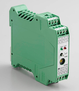
Santest GY Series : GYHC Controller
High accuracy analogue controller
Specifications
| Resolution (position) | 16bit (1/65536) (*1) ≦0.01%FS (*2) |
|---|---|
| Position(OUT1) (OUT2:option) |
0-10V (Max.5mA, Min.2kΩ) or 4-20mA (load:Max.500Ω) |
| Velocity(OUT2) (option) |
±10V or 4-20mA |
| Alarm(*3) | Open collector 0.1A 30VDC(*3) |
| Power supply | Std:+24VDC±5% (150mA) Option:+15VDC±5% (250mA) (*4) |
| Sampling freq. | Std 1kHz (up to stroke 1000mm) |
| Temp. drift | ≦±10ppmFS/°C |
| Operating temp. | 0°C-+65°C |
| Storage temp. | -20°C-+85°C |
*The above mentioned accuracy applies to sensors with an effective stroke of 300 mm or more.
(*1)associated probe:GYSE-R, GYcRS, GYMR5, GYFRS
(*2)associated probe:GYGS, GYMS, GYPM, GYHR, GYcRP, GYKM
(*3)Cable cut and magnet missing
(*4)GYcRP probe only (Total rod length ≦1500mm)
Model No.

①Probe
SR:GYSE-R
RS:GYcRS
R5:GYMR5
FS:GYFRS
HR:GYHR
GS:GYGS
PM:GYPM
RP:GYcRP
MS:GYMS
PR:GYPMR
P2:GYPE2K
KM:GYKM
KRS:GYKM-RS
②Effective stroke(mm)
③Thread dead zone
S:50mm(STD)
□:□mm(option)(specified by customers)
④Associated magnet or float
| magnet | float |
|---|---|
| M2P :No.2P (STD) M2PN :No.2PN MG0 :No.Φ M0SM :No.ΦSPM M0LM :No.ΦLPM M3 :No.3 M11 :No.11 M11N :No.11N T142 :No.T14-M2 T144 :No.T14-M4 T162 :No.T16-M2 T163 :No.T16-M3 MG□ :other magnet |
F28S :Φ28 SS316 F30S :Φ30 SS316L F40S :Φ40 SS316(B) F42S :Φ42.5 SS316 F50S :Φ50 SS316 F54S :Φ54 SS304 F25N :RF-A10 plastic F28N :RF-A6 plastic FL□ :other float |
⑤Position output(OUT1)
AD:0-10V(When magnet moves toward tip, output increase)
AR:10-0V(When magnet moves toward tip, output decrease)
BD:4-20mA(When magnet moves toward tip, output increase)
BR:20-4mA(When magnet moves toward tip, output decrease)
CD□□:bipolar output(-□V-+□V)
(for example CD10:-10V-+10V)
CR□□:bipolar output(+□V–□V)
(for example CR05:+5V–5V)
V Z/F:option (specified voltage)
(for example V1/5:1-5V, V9.5/0.5:9.5-0.5V)
I Z/F:option (specified current)
(for example I5.2/20:5.2-20mA, I18/5:18-5mA)
【Z=output at zero position, F=output at full position】
⑥additional analogue output(OUT2)
・N:without option(STD)
・position output:select from ⑤
・velocity output(Note1)
VA[ ]:±10V
WB[ ]:4-20mA
[ ]:max velocity (1.00-999mm/sec)
(ex.9R99: max velocity=9.99mm/sec)
(Note1)
VA:When magnet stops, output is 0V.
When moving toward probe tip, +10V.
WB:When magnet stops, output is 4mA.
When moving in any direction, 20mA.
⑦Power supply
24S:+24VDC(STD)
15S:+15VDC(Option)(GYcRP probe only)
⑧Option
2ME:2 magnets, each magnet position
2MR:2 magnets, relative distance between 2pcs(OUT1)
X2:higher sampling freq. double
X3:higher sampling freq. triple
X4:higher sampling freq. qaudruple (3.75kHz)
<For higher sampling option>
・probe tip DZ needs extra 30mm
・for example, stroke : 500mm, standard is 1kHz and with X2 option, it is 2kHz.
Dimensions


