Santest GY Series : GYHR Probe / GYMNC Controller
High ambient temperature
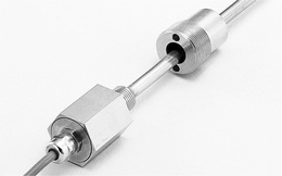
Electronic parts inside are minimized, yet provide high performance and reliability in the application. Cable used has reinforced silicon rubber sheath which stands ambient temperatures up to 150°C. Max cable extension is 100m.
GYHR probe can also be used in combination with GYHC and GYDC-05 controller, which provides velocity output or digital output.
Specifications
| Non-linearity | ≦±0.1%FS TYP |
|---|---|
| Resolution | ≦0.01%FS |
| Repeatability | ≦±0.05%FS |
| Temp. drift | ≦±70ppmFS/°C(probe) ≦±50ppmFS/°C (controller) |
| Voltage output | 0-10V or 10-0V (output current:Max.5mA, load:Min.2kΩ) |
| Current output | 4-20m or 20-4mA (load:Max.500Ω) |
| Alarm output | not available |
| Power supply | +24(±2)VDC (100mA) |
| Sampling freq. | Std 1kHz (up to stroke 1000mm) |
| Max. Pressure | 35MPa (probe rod) |
| Operating temp. | -5°C-+100°C (probe) 0°C-+60°C(controller) |
| Storage temp. | -40°C-+120°C |
| Vibration | 6G (or 40Hz 2mmPP) |
| Shock | 50G (2msec) |
| IP grade | IP64 (probe) |
| Cable | Std 1.5m (Option Max.100m) |
*The above mentioned accuracy applies to sensors with an effective stroke of 300mm or more.
*Zero/Gain adjustment by trimmer of controller are possible, std within ±3%FS.
Model No.

①Effective stroke
15-2000mm
*In case of an effective stroke of 1000mm or more, it needs screw side dead zone length of 120mm and tip dead zone length of 120mm.
②Thread dead zone
S:50mm(STD)
□:□mm(option)(specified by customers)
③Tip dead zone
S:90mm/100mm(STD)
*S (STD length) depends on the selected magnet or float in ⑤.
| tip DZ | magnet | float |
|---|---|---|
| 90mm | F28S, F30S | |
| 100mm | T142, T162 | F40S, F42S, F50S |
□:□mm(option)(specified by customers)
④Thread/Rod diameter
K8 :M16xP1.5, rod Φ8(STD)
K :M16xP1.5, rod Φ10
*In case of stroke longer than 1000mm, rod Φ10 is recommended.
⑤Associated magnet or float
| magnet | float |
|---|---|
| T142 :No.T14-M2 T162 :No.T16-M2 MG□ :other magnet |
F28S :Φ28 SS316 F30S :Φ30 SS316L F40S :Φ40 SS316(B) F42S :Φ42.5 SS316 F50S :Φ50 SS316 F54S :Φ54 SS304 FL□ :other float |
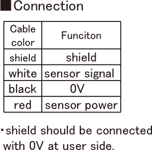
⑥Cable connection
G□F:pigtail / cable end : free
G□A:pigtail / cable end : with connector for relay
(□:cable length(m))
⑦Position output
AD:0-10V(When magnet moves toward tip, output increase)
AR:10-0V(When magnet moves toward tip, output decrease)
BD:4-20mA(When magnet moves toward tip, output increase)
BR:20-4mA(When magnet moves toward tip, output decrease)
CD□□:bipolar output(-□V-+□V)
(for example CD10:-10V-+10V)
CR□□:bipolar output(+□V–□V)
(for example CR05:+5V–5V)
⑧Option
blank:without option
H2:probe rod only 200℃
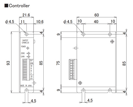
Dimensions